GE HEALTHCARE
DIRECTION 5394152, Revision 5
LOGIQ™ P6/P6 PRO SERVICE MANUAL
Chapter 8 - Page 8-55
8-2-19 Top Bottom Cover
8-2-19-1 Tools
• Common Phillips screwdrivers
• Stubby screwdriver (Flat tip and Cross tip)
8-2-19-2 Preparations
• Shut down the system and switch off the main breaker.
8-2-19-3 Removal procedure
1.) Remove the Dummy Cover L/R. Refer to the 8-2-23 "Dummy Cover L / R" on page 8-61.
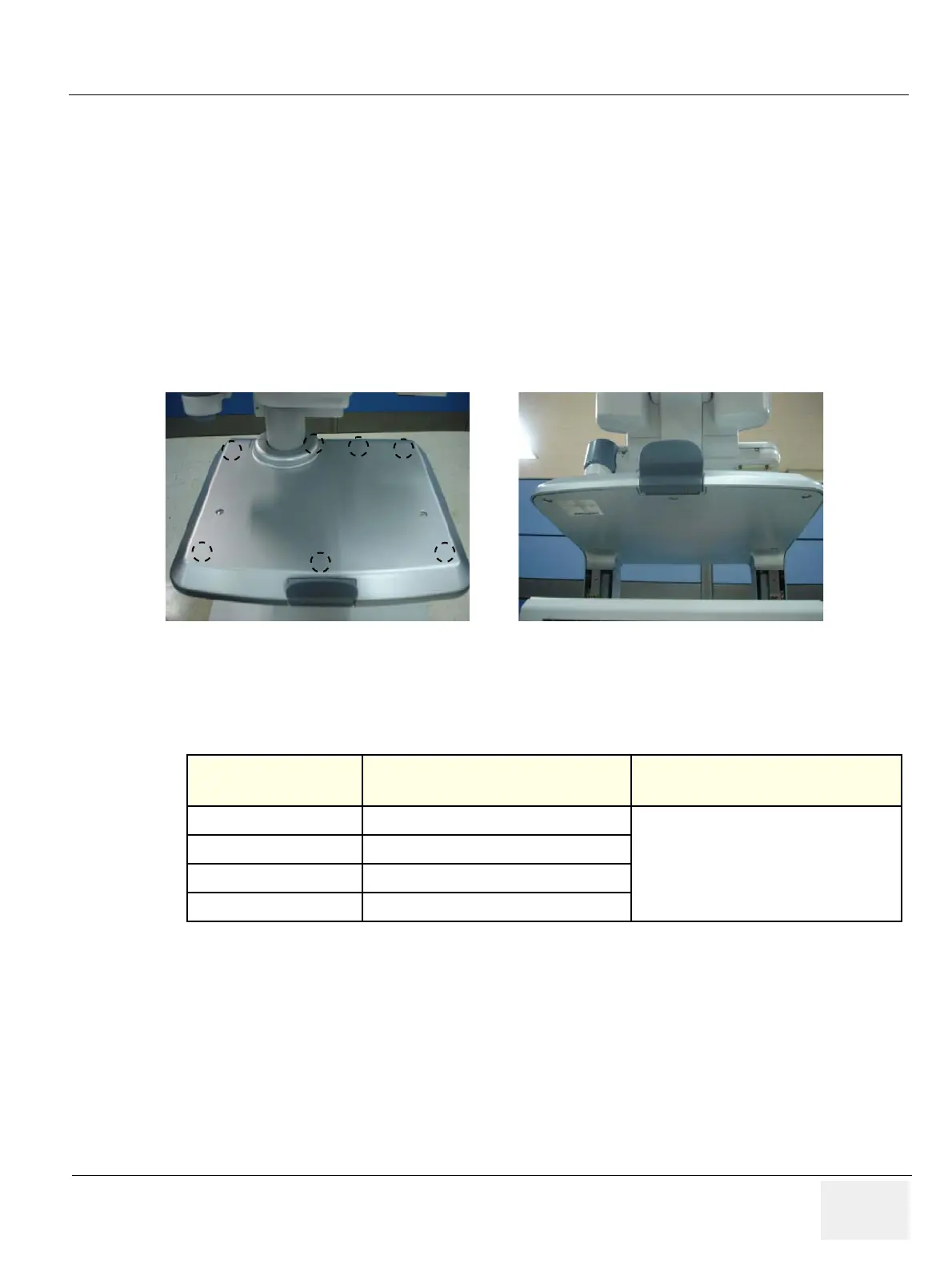
2.) Unscrew 7 screws (1-7) from the bottom of the top cover.
3.) Remove the Top Bottom Cover.
4.) Perform the following functional tests. If all are successful, include the debrief script provided below.
8-2-19-4 Mounting Procedure
Install the new parts in the reverse order of removal.
Figure 8-94 Top bottom cover
Table 8-20 Functional Tests
Service Manual
Section
Functional Test / Diagnostic Test Debrief Script
Section 4-3-1
Power On/Boot Up
“Service Manual, Direction
5394152, Rev 1+, Section 8-2-19. Equipment
passed all required tests and is ready for use. “
Section 4-3-2
Power Off / Shutdown
Section 4-8-1
Cover Parts Function Validation
Section 10-5-5
Physical Inspection

 Loading...


