GE HEALTHCARE
DIRECTION 5394152, Revision 5
LOGIQ™ P6/P6 PRO SERVICE MANUAL
Page 8-12 Section 8-2 - DISASSEMBLY/RE-ASSEMBLY
8-2-4 New Articulation arm with cover installation Procedure
8-2-4-1 Tools
• Common Phillips screwdrivers
• Allen/Unbraco wrench
• Stubby screwdriver (Flat tip and Cross tip)
8-2-4-2 Preparations
• Shut down the system and switch off the main breaker.
• Maneuver control console to a suitable position for removing the monitor.
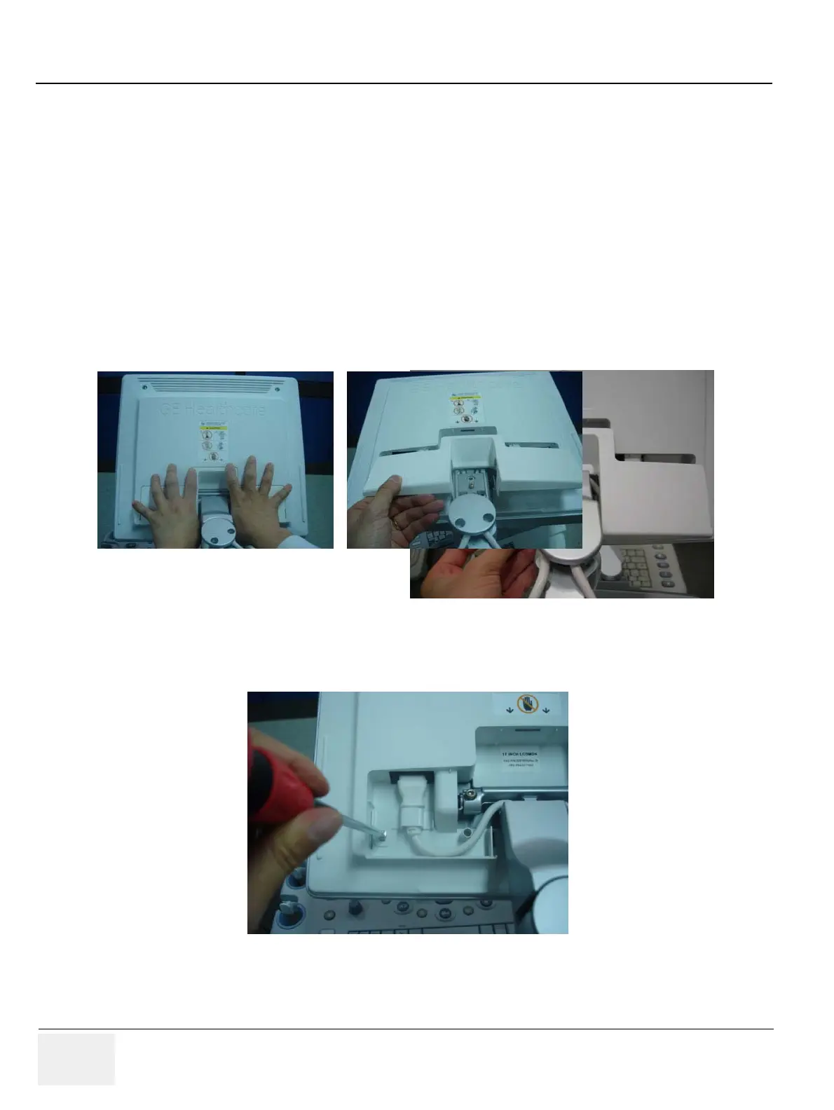
8-2-4-3 Removal procedure
1.) Remove the LCD cable cover.
2.) Unscrew 1 screw (2306565, BH M4x16 WHT) to remove the power cord bracket assembled under
the LCD cable cover.
Figure 8-17 Removing the LCD cable cover
Figure 8-18 Removing the power cord bracket

 Loading...


