EasyManuals Logo

GE LOGIQ P6 Series User Manual

GE LOGIQ P6 Series
484 pages
To Next Page IconTo Next Page
To Previous Page IconTo Previous Page
Page #229 background imageLoading...
Page #229 background image
GE HEALTHCARE
DIRECTION 5394152, Revision 5
LOGIQ™ P6/P6 PRO SERVICE MANUAL
Chapter 8 - Page 8-3
8-2-1 17 Inch monitor cover set
8-2-1-1 Tools
Common pilIips screwdrivers
Allen/Unbraco wrench
Stubby screwdriver (Flat tip and Cross tip)
8-2-1-2 Removal procedure
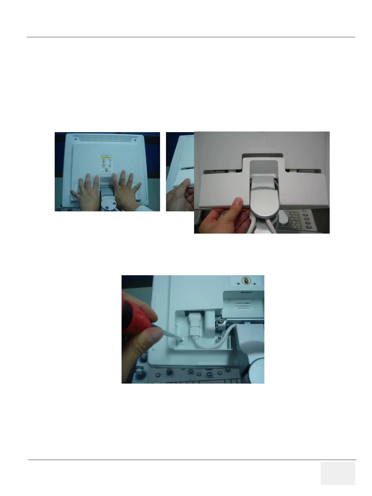
1.) Remove the 17" LCD cable cover.
2.) Unscrew 1 screw (2306565, BH M4x16 WHT) to remove the power cord bracket assembled under
the 17" LCD cable cover.
Figure 8-1 Removing the 17" LCD cable cover
Figure 8-2 Removing the power cord bracket

Table of Contents

Questions and Answers:

Question and Answer IconNeed help?

Do you have a question about the GE LOGIQ P6 Series and is the answer not in the manual?

GE LOGIQ P6 Series Specifications

General IconGeneral
Power Supply100-240 VAC, 50/60 Hz
Imaging ModesB-Mode, M-Mode, Color Doppler, Power Doppler
ApplicationsVascular, Musculoskeletal
Operating Temperature10°C to 40°C
Display15-inch LCD
Relative Humidity20% to 80% (non-condensing)

Related product manuals