EasyManuals Logo

GE LOGIQ P6 Series User Manual

GE LOGIQ P6 Series
484 pages
To Next Page IconTo Next Page
To Previous Page IconTo Previous Page
Page #276 background imageLoading...
Page #276 background image
GE HEALTHCARE
DIRECTION 5394152, Revision 5
LOGIQ™ P6/P6 PRO SERVICE MANUAL
Page 8-50 Section 8-2 - DISASSEMBLY/RE-ASSEMBLY
8-2-15 Front Cover
8-2-15-1 Tools
Common Phillips screwdrivers
8-2-15-2 Preparations
Shut down the system and switch off the main breaker.
8-2-15-3 Removal procedure
1.) Remove the Left and Right side covers. Refer to the 8-2-14 "Right or Left Side Cover" on page 8-48
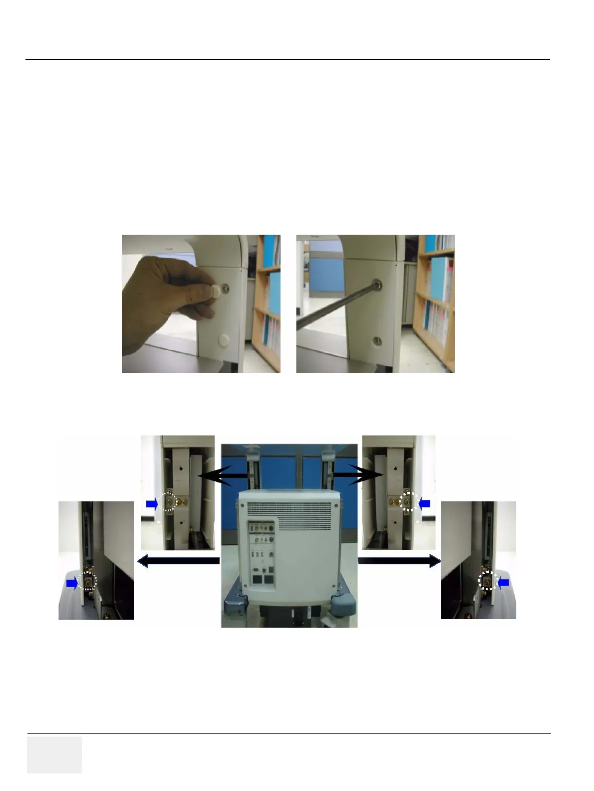
2.) Remove the dummy left and right covers.
3.) Remove the two screws on each side of the back of the front cover.
Figure 8-88 Screws of Dummy Cover
Figure 8-89 Screws of the front cover

Table of Contents

Questions and Answers:

Question and Answer IconNeed help?

Do you have a question about the GE LOGIQ P6 Series and is the answer not in the manual?

GE LOGIQ P6 Series Specifications

General IconGeneral
Power Supply100-240 VAC, 50/60 Hz
Imaging ModesB-Mode, M-Mode, Color Doppler, Power Doppler
ApplicationsVascular, Musculoskeletal
Operating Temperature10°C to 40°C
Display15-inch LCD
Relative Humidity20% to 80% (non-condensing)

Related product manuals