GE HEALTHCARE
DIRECTION 5394152, Revision 5
LOGIQ™ P6/P6 PRO SERVICE MANUAL
Chapter 3 - Page 3-19
3-6-4-1 External I/O Pin Outs
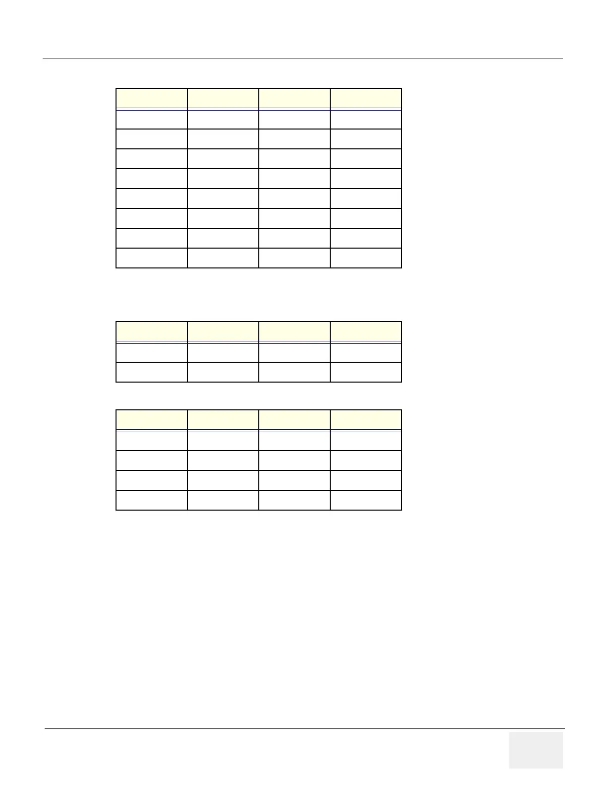
Pin No. Signal Pin No. Signal
1RED9 N/A
2 GREEN 10 SGND
3BLUE11 N/A
4N/A12N/A
5 GND 13 HSYNC
6 RGND 14 VSYNC
7 GGND 15 N/A
8BGND
Table 3-6 Pin Assignments of DB15 connector for External VGA
Pin No. Signal Pin No. Signal
1+5 VDC3DATA +
2 DATA - 4 GND
Table 3-7 Pin Assignments of USB
Pin No. Signal Pin No. Signal
1TX+5 NC
2 TX- 6 RX-
3RX+7 NC
4NC8NC
Table 3-8 Pin Assignments of Ethernet

 Loading...


