GE HEALTHCARE
DIRECTION 5394152, Revision 5
LOGIQ™ P6/P6 PRO SERVICE MANUAL
Chapter 8 - Page 8-33
8-2-5 New Articulation cover set installation Procedure
8-2-5-1 Tools
• Common Phillips screwdrivers
• Stubby screwdriver (Flat tip and Cross tip)
8-2-5-2 Preparations
• Shut down the system and switch off the main breaker.
• Maneuver control console to a suitable position for removing the monitor.
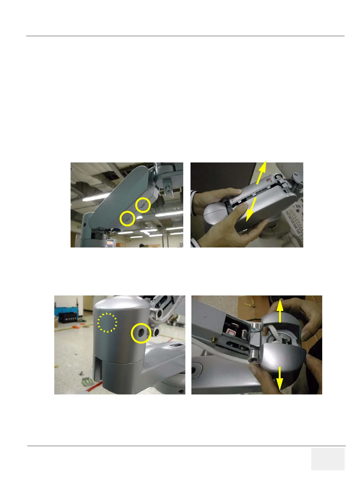
8-2-5-3 Removal procedure
1.) ARM COVER L & R
Unscrew 2 screws (2337572, FH M3x6 WHT) to remove the Arm cover L & R.
2.) ARM CAM COVER L & R
Unscrew 2 screws (2159632, BH M4x6 WHT) to remove the Arm cam cover L & R.
Figure 8-62 Removing the Arm cover L & Arm cover R
Figure 8-63 Removing the Arm cam cover L & Arm cam cover R

 Loading...


