EasyManuals Logo

GE LOGIQ P6 Series User Manual

GE LOGIQ P6 Series
484 pages
To Next Page IconTo Next Page
To Previous Page IconTo Previous Page
Page #466 background imageLoading...
Page #466 background image
GE HEALTHCARE
DIRECTION 5394152, Revision 5
LOGIQ™ P6/P6 PRO SERVICE MANUAL
Page 10-16 Section 10-6 - Electrical Safety Tests
10-6-4-2 Dale 600 - Ground Continuity
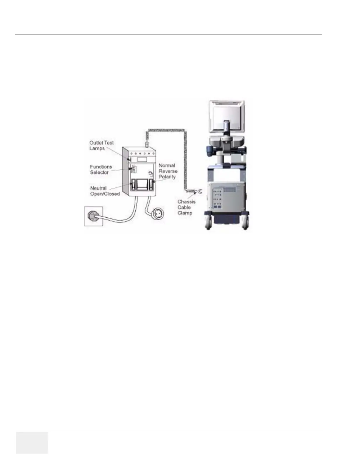
The Dale 600 measures line cord resistance from the third pin of the attachment plug to the meter’s
Chassis Cable clamp. Test the grounding continuity of the system to all exposed metal parts in
accordance with the IEC 601-1.1 procedure as above. refer to the Dale 600 Instruction Manual for meter
self tests and operation. Record measured resistance of the grounding continuity. The ground wire
resistance should be less than 0.2 (Use any safety analyzer.)
Figure 10-4 Dale 600 Ground Continuity Test

Table of Contents

Questions and Answers:

Question and Answer IconNeed help?

Do you have a question about the GE LOGIQ P6 Series and is the answer not in the manual?

GE LOGIQ P6 Series Specifications

General IconGeneral
Power Supply100-240 VAC, 50/60 Hz
Imaging ModesB-Mode, M-Mode, Color Doppler, Power Doppler
ApplicationsVascular, Musculoskeletal
Operating Temperature10°C to 40°C
Display15-inch LCD
Relative Humidity20% to 80% (non-condensing)

Related product manuals