GE HEALTHCARE
DIRECTION 5394152, Revision 5
LOGIQ™ P6/P6 PRO SERVICE MANUAL
Chapter 10 - Page 10-27
10-6-9-4 No Meter Probe Adapter Procedure
Follow these steps to test each transducer for leakage current.
1.) Turn the LOGIQ™ P6/P6 Pro unit OFF.
2.) Plug the unit into the test meter, and the meter into the tested AC wall outlet.
3.) Plug the external probe into the meter's (Dale 600) “EXTERNAL” connector.
4.) Set the meter's “FUNCTION” switch to EXTERNAL position.
5.) Connect the probe for test with the connector of the console.
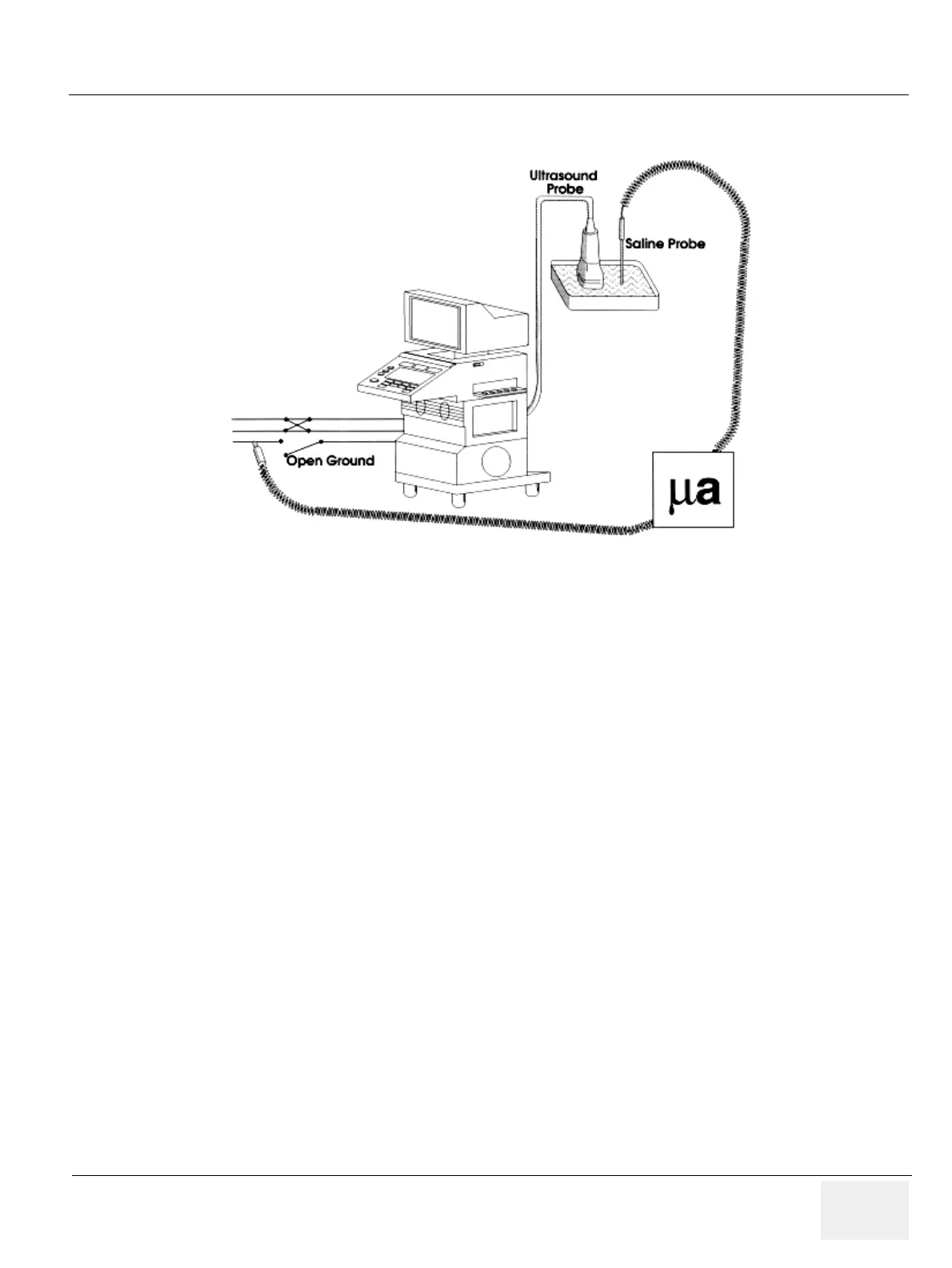
6.) Add the saline probe and the imaging area of the probe into the saline bath.
7.) Have unit power ON for the first part; turn it OFF for the second half.
8.) Depress the ISO TEST rocker switch and record the highest current reading.
9.) Follow the test conditions described in Table 10-23 for every transducer.
10.)Keep a record of the results with other hand copies of PM data.
Figure 10-11 Check Without Probe Adapter

 Loading...


