EasyManuals Logo

GE LOGIQ P6 Series User Manual

GE LOGIQ P6 Series
484 pages
To Next Page IconTo Next Page
To Previous Page IconTo Previous Page
Page #302 background imageLoading...
Page #302 background image
GE HEALTHCARE
DIRECTION 5394152, Revision 5
LOGIQ™ P6/P6 PRO SERVICE MANUAL
Page 8-76 Section 8-2 - DISASSEMBLY/RE-ASSEMBLY
8-2-31 SOM Replacement
8-2-31-1 Tools
Common Phillips screwdrivers
8-2-31-2 Preparations
Shut down the system and switch off the main breaker.
8-2-31-3 Removal procedure
1.) Remove the Side Right Cover. Refer to the 8-2-14 "Right or Left Side Cover" on page 8-48.
2.) Remove the EMI Cover R. Refer to the 8-2-24 "EMI Cover L and R" on page 8-63.
3.) Remove the SYSCOMML Assy. Refer to the 8-2-30 "SYSCONML Assy" on page 8-73.
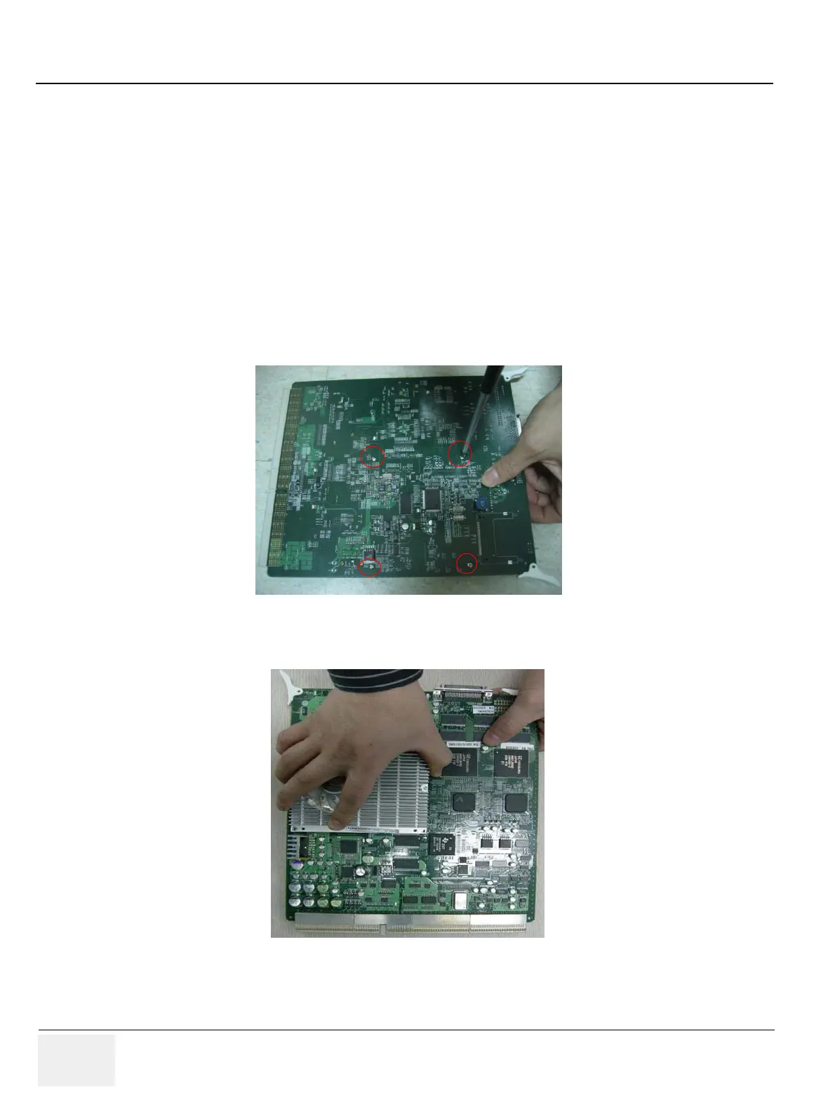
4.) Unscrews 4 screws.
5.) Remove the SOM Assy.
Figure 8-116 4 screws for SOM on SYSCON
Figure 8-117 Remove a SOM from SYSCONML Assy

Table of Contents

Questions and Answers:

Question and Answer IconNeed help?

Do you have a question about the GE LOGIQ P6 Series and is the answer not in the manual?

GE LOGIQ P6 Series Specifications

General IconGeneral
Power Supply100-240 VAC, 50/60 Hz
Imaging ModesB-Mode, M-Mode, Color Doppler, Power Doppler
ApplicationsVascular, Musculoskeletal
Operating Temperature10°C to 40°C
Display15-inch LCD
Relative Humidity20% to 80% (non-condensing)

Related product manuals