EasyManuals Logo

GE LOGIQ P6 Series User Manual

GE LOGIQ P6 Series
484 pages
To Next Page IconTo Next Page
To Previous Page IconTo Previous Page
Page #315 background imageLoading...
Page #315 background image
GE HEALTHCARE
DIRECTION 5394152, Revision 5
LOGIQ™ P6/P6 PRO SERVICE MANUAL
Chapter 8 - Page 8-89
8-2-41 NEST FAN Assy
8-2-41-1 Tools
Common Phillips screwdrivers
8-2-41-2 Preparations
Shut down the system and switch off the main breaker.
8-2-41-3 Removal procedure
1.) Remove the Left and Right Covers. Refer to the 8-2-14 "Right or Left Side Cover" on page 8-48.
2.) Remove the EMI Right and Left covers. Refer to the 8-2-24 "EMI Cover L and R" on page 8-63.
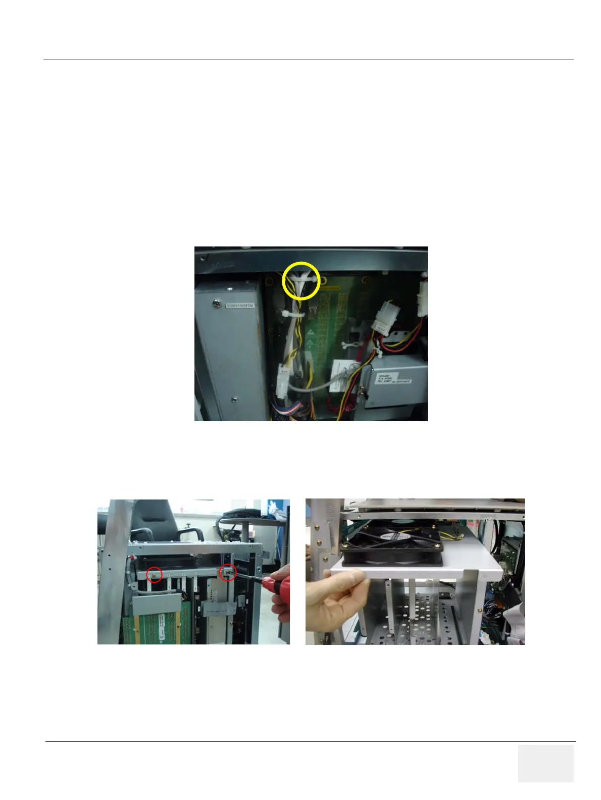
3.) Cut the cable tie, and unplug the ‘FAN’ connector.
4.) Unscrews the two screws.
5.) Pull out the FAN assy forward from the nest.
Figure 8-131 Connector and Screw2 screws on the Nest Fan
Figure 8-132 Pull out the nest fan

Table of Contents

Questions and Answers:

Question and Answer IconNeed help?

Do you have a question about the GE LOGIQ P6 Series and is the answer not in the manual?

GE LOGIQ P6 Series Specifications

General IconGeneral
Power Supply100-240 VAC, 50/60 Hz
Imaging ModesB-Mode, M-Mode, Color Doppler, Power Doppler
ApplicationsVascular, Musculoskeletal
Operating Temperature10°C to 40°C
Display15-inch LCD
Relative Humidity20% to 80% (non-condensing)

Related product manuals