GE HEALTHCARE
DIRECTION 5394152, Revision 5
LOGIQ™ P6/P6 PRO SERVICE MANUAL
Page 8-36 Section 8-2 - DISASSEMBLY/RE-ASSEMBLY
8-2-5-3 Removal procedure (cont’d)
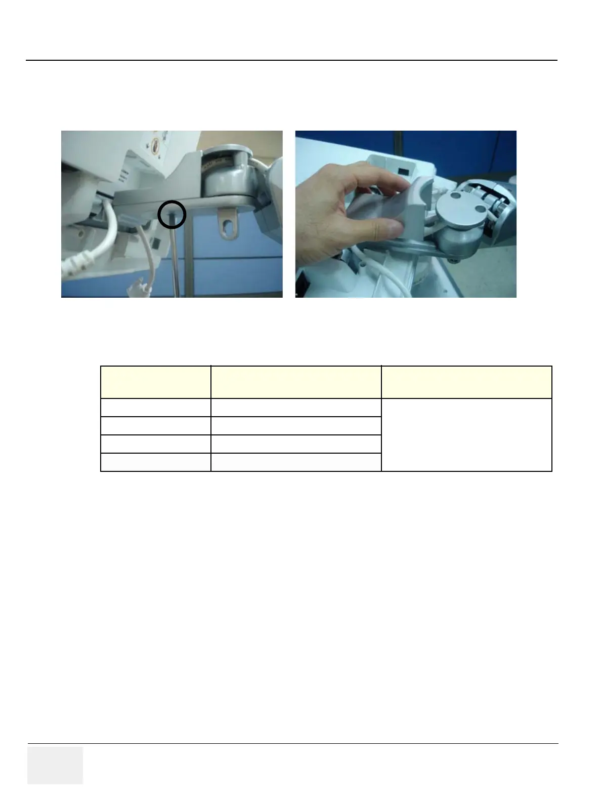
7.) ARM FOLD COVER
Unscrew 1 screw (2329677, TAP M4X16) to remove the Arm fold cover.
8.) Perform the following functional tests. If all are successful, include the debrief script provided below.
8-2-5-4 Mounting procedure
Install the each of the new part in the reverse order of removal procedure.
Figure 8-69 Removing the Arm fold cover
Table 8-6 Functional Tests
Service Manual
Section Functional Test / Diagnostic Test Debrief Script
Section 4-3-1
Power On/Boot Up
“Service Manual, Direction
5394152, Rev 1+, Section 8-2-5. Equipment
passed all required tests and is ready for use. “
Section 4-3-2
Power Off / Shutdown
Section 4-8-1
Cover Parts Function Validation
Section 10-5-5
Physical Inspection

 Loading...


