GE HEALTHCARE
DIRECTION 5394152, Revision 5
LOGIQ™ P6/P6 PRO SERVICE MANUAL
Chapter 8 - Page 8-87
8-2-40 DVD R/W Drive
8-2-40-1 Tools
• Common Phillips screwdrivers
• Clock screw driver
8-2-40-2 Preparations
• Shut down the system and switch off the main breaker.
8-2-40-3 Removal procedure
1.) Remove the side Left and Right covers. Refer to the 8-2-14 "Right or Left Side Cover" on page 8-48.
2.) Remove EMI Left cover. Refer to the 8-2-24 "EMI Cover L and R" on page 8-63.
3.) Remove the HDD assy. Refer to the 8-2-43 "SATA HDD Assy" on page 8-93.
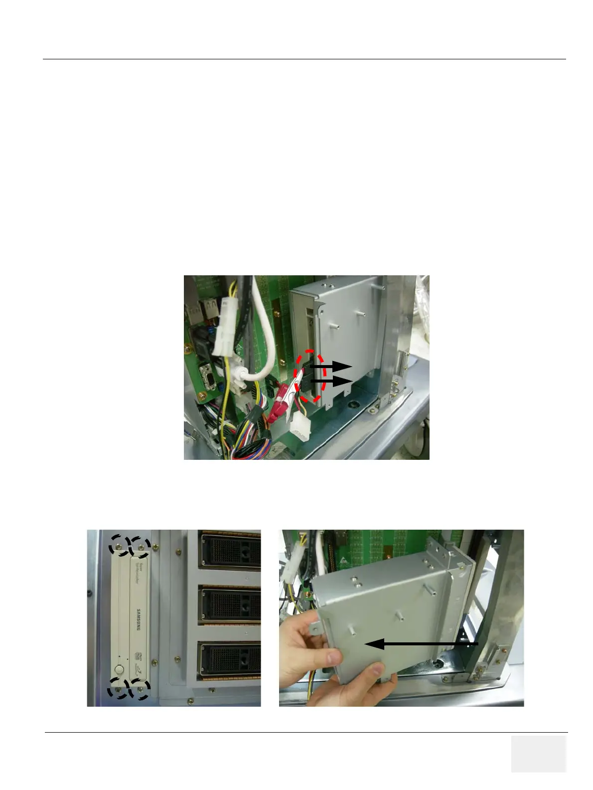
4.) Disconnect ODD SATA Power Cable and SATA Cable. From DVD Drive.
5.) Remove the Front Cover. Refer to the 8-2-15 "Front Cover" on page 8-50.
6.) Unscrew the 4 screws on the front of the DVD drive and remove the DVD Assy.
Figure 8-128 ODD SATA Power Cable and SATA cable of DVD Drive
Figure 8-129 Unscrew 4screws and remove the DVD Assy
SATA Cable
ODD SATA
Power Cable

 Loading...


