EasyManuals Logo

GE LOGIQ P6 Series User Manual

GE LOGIQ P6 Series
484 pages
To Next Page IconTo Next Page
To Previous Page IconTo Previous Page
Page #394 background imageLoading...
Page #394 background image
GE HEALTHCARE
DIRECTION 5394152, Revision 5
LOGIQ™ P6/P6 PRO SERVICE MANUAL
Page 8-168 Section 8-7 - Mechanical Option Installation instruction
8-7-9 Color Printer Fixture Middle installation - UP-D25MD Printer (cont’d)
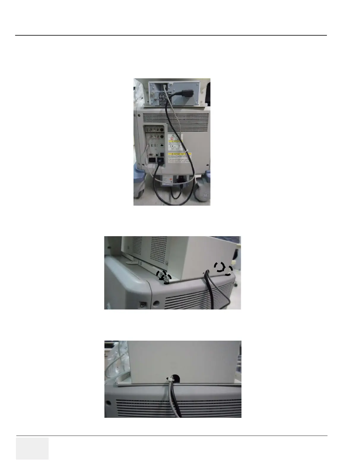
4.) Connect the USB cable and Power cable from the color printer to the system as shown in the figure
below.
5.) Install Mid Color Cable Bracket and screw 4 screws(2159633, BH M4X8) to fix it.
6.) Tie the cables using the tie wrap as illustrated in the figure below.
Figure 8-260 Color Printer Fixture Middle installation
Figure 8-261 Color Printer Fixture Middle installation
Figure 8-262 Color Printer Fixture Middle installation

Table of Contents

Questions and Answers:

Question and Answer IconNeed help?

Do you have a question about the GE LOGIQ P6 Series and is the answer not in the manual?

GE LOGIQ P6 Series Specifications

General IconGeneral
Power Supply100-240 VAC, 50/60 Hz
Imaging ModesB-Mode, M-Mode, Color Doppler, Power Doppler
ApplicationsVascular, Musculoskeletal
Operating Temperature10°C to 40°C
Display15-inch LCD
Relative Humidity20% to 80% (non-condensing)

Related product manuals