EasyManuals Logo

GE LOGIQ P6 Series User Manual

GE LOGIQ P6 Series
484 pages
To Next Page IconTo Next Page
To Previous Page IconTo Previous Page
Page #401 background imageLoading...
Page #401 background image
GE HEALTHCARE
DIRECTION 5394152, Revision 5
LOGIQ™ P6/P6 PRO SERVICE MANUAL
Chapter 8 - Page 8-175
8-7-12 Printer VCR DVD fixture Top installation - CP900 Printer (cont’d)
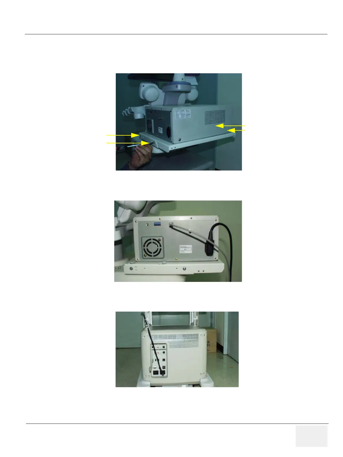
4.) Screw 2 screws(2159633, BH M4x8 WHT) on each sides to fix the color printer with base bracket
to the color printer top bracket.
5.) Connect the USB from the color printer as shown in the figure below.
6.) Connect the cable from the color printer to the system.
Figure 8-278 Printer VCR DVD Fixture Top installation
Figure
8-279 Printer VCR DVD Fixture Top installation
Figure 8-280 Printer VCR DVD Fixture Top installation
(1)
(2)
(3)
(4)

Table of Contents

Questions and Answers:

Question and Answer IconNeed help?

Do you have a question about the GE LOGIQ P6 Series and is the answer not in the manual?

GE LOGIQ P6 Series Specifications

General IconGeneral
Power Supply100-240 VAC, 50/60 Hz
Imaging ModesB-Mode, M-Mode, Color Doppler, Power Doppler
ApplicationsVascular, Musculoskeletal
Operating Temperature10°C to 40°C
Display15-inch LCD
Relative Humidity20% to 80% (non-condensing)

Related product manuals