GE HEALTHCARE
DIRECTION 5394152, Revision 5
LOGIQ™ P6/P6 PRO SERVICE MANUAL
Page 8-178 Section 8-7 - Mechanical Option Installation instruction
8-7-13-1 VCR Remote Port Configuration (cont’d)
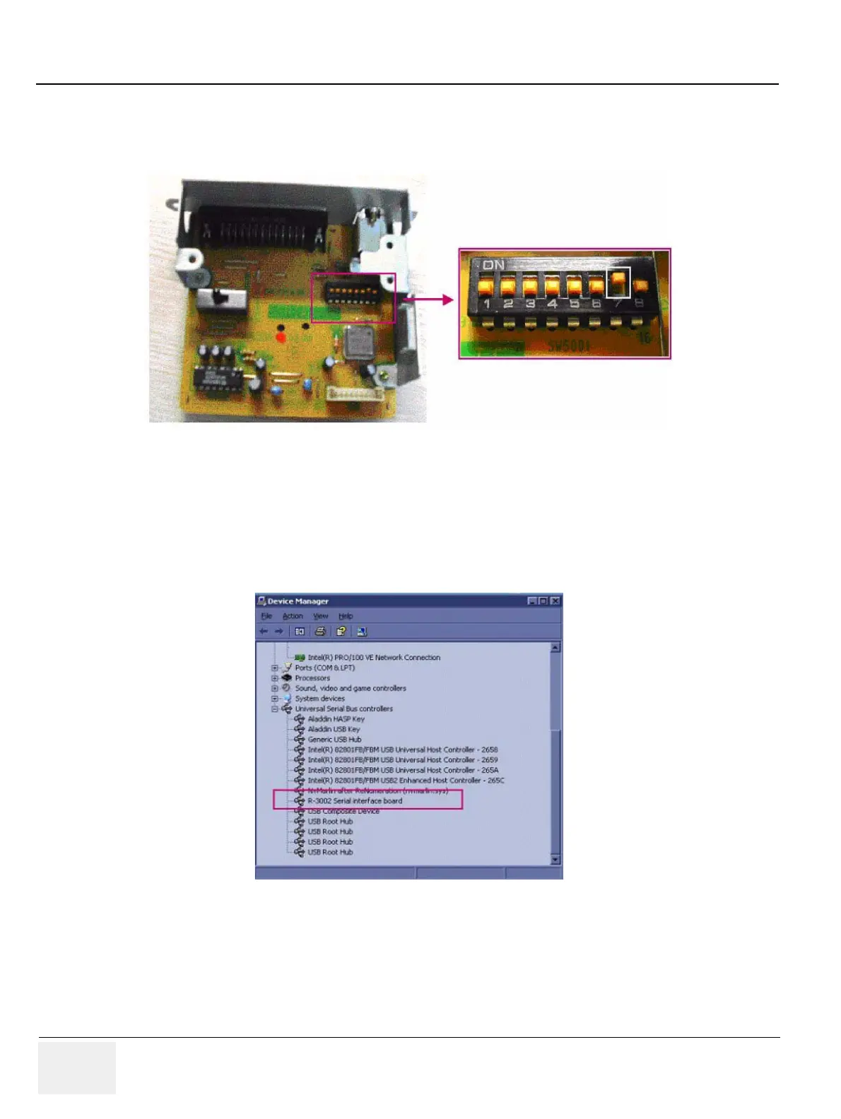
4.) Set the DIP switch on the VCR remote control panel. The SW 7 in DIP switch should be set to “ON”
position for the USB remote control.
5.) Insert the remote control module into the VCR and connect the USB cable between the “Remote”
USB on the console rear panel and USB port of VCR.
6.) Plug the service dongle and turn on the VCR and System.
7.) Login to maintenance mode and open the device manager.
8.) Check if the VCR remote device is identified by OS.
Figure 8-284 DIP Switch on the Panel
Figure 8-285 Remote device in the device manager

 Loading...


