EasyManuals Logo

GE LOGIQ P6 Series User Manual

GE LOGIQ P6 Series
484 pages
To Next Page IconTo Next Page
To Previous Page IconTo Previous Page
Page #406 background imageLoading...
Page #406 background image
GE HEALTHCARE
DIRECTION 5394152, Revision 5
LOGIQ™ P6/P6 PRO SERVICE MANUAL
Page 8-180 Section 8-7 - Mechanical Option Installation instruction
8-7-13-2 Bracket Installation (cont’d)
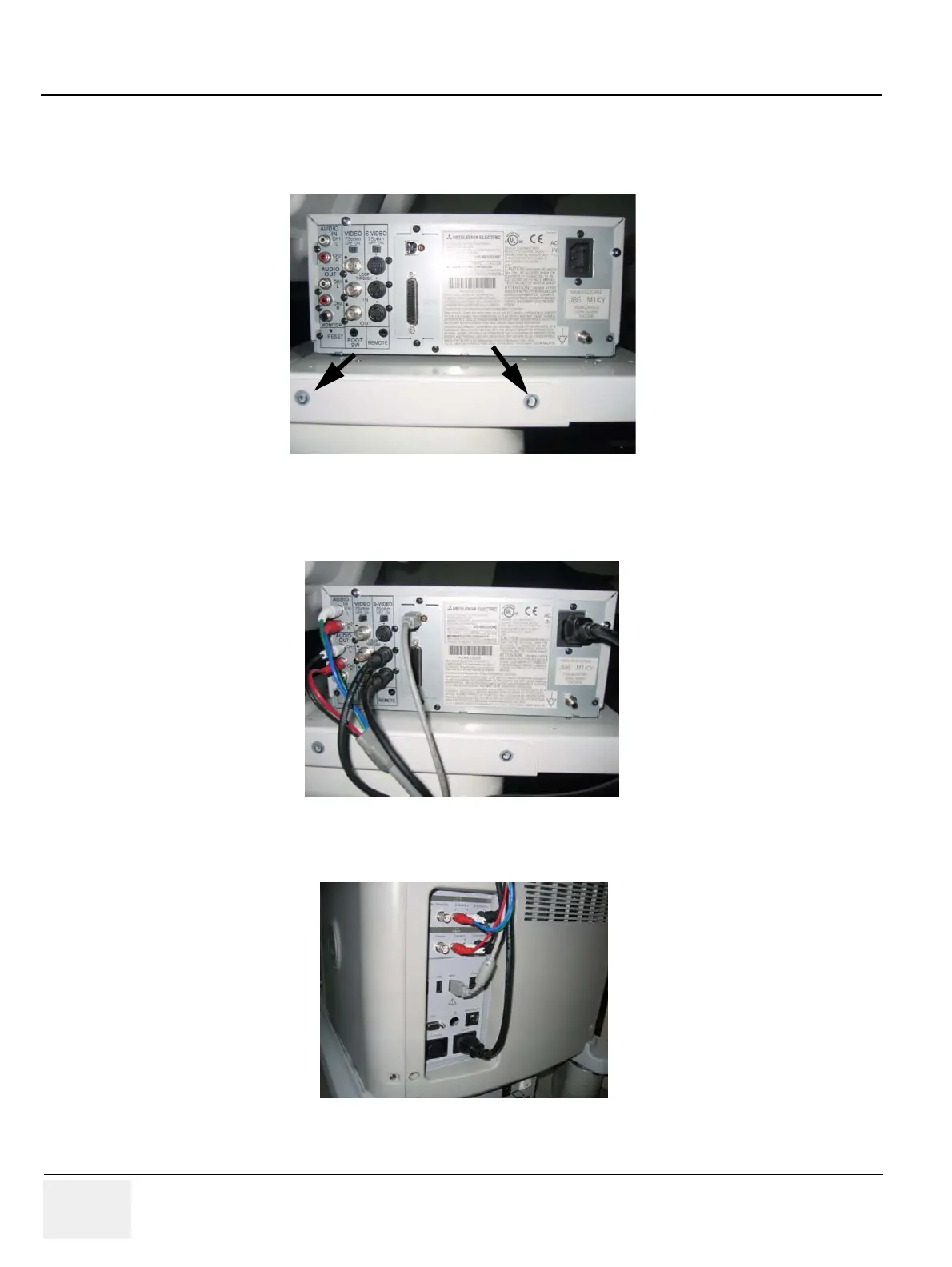
4.) Screw 2 screws(2159633, BH M4x8 WHT) on each side of the system to fix the VCR recorder with
base bracket to the VCR top bracket.
5.) Connect the cables (Power Cable, USB cable, S-VHS Cable, and Sound cables) from the VCR to
the system.
6.) Connect the cables to the system on the rear panel.
Figure 8-289 Printer VCR DVD Fixture Top installation
Figure 8-290 Printer VCR DVD Fixture Top installation
F
igure 8-291 Printer VCR DVD Fixture Top installation

Table of Contents

Questions and Answers:

Question and Answer IconNeed help?

Do you have a question about the GE LOGIQ P6 Series and is the answer not in the manual?

GE LOGIQ P6 Series Specifications

General IconGeneral
Power Supply100-240 VAC, 50/60 Hz
Imaging ModesB-Mode, M-Mode, Color Doppler, Power Doppler
ApplicationsVascular, Musculoskeletal
Operating Temperature10°C to 40°C
Display15-inch LCD
Relative Humidity20% to 80% (non-condensing)

Related product manuals