179
Calculation Formula
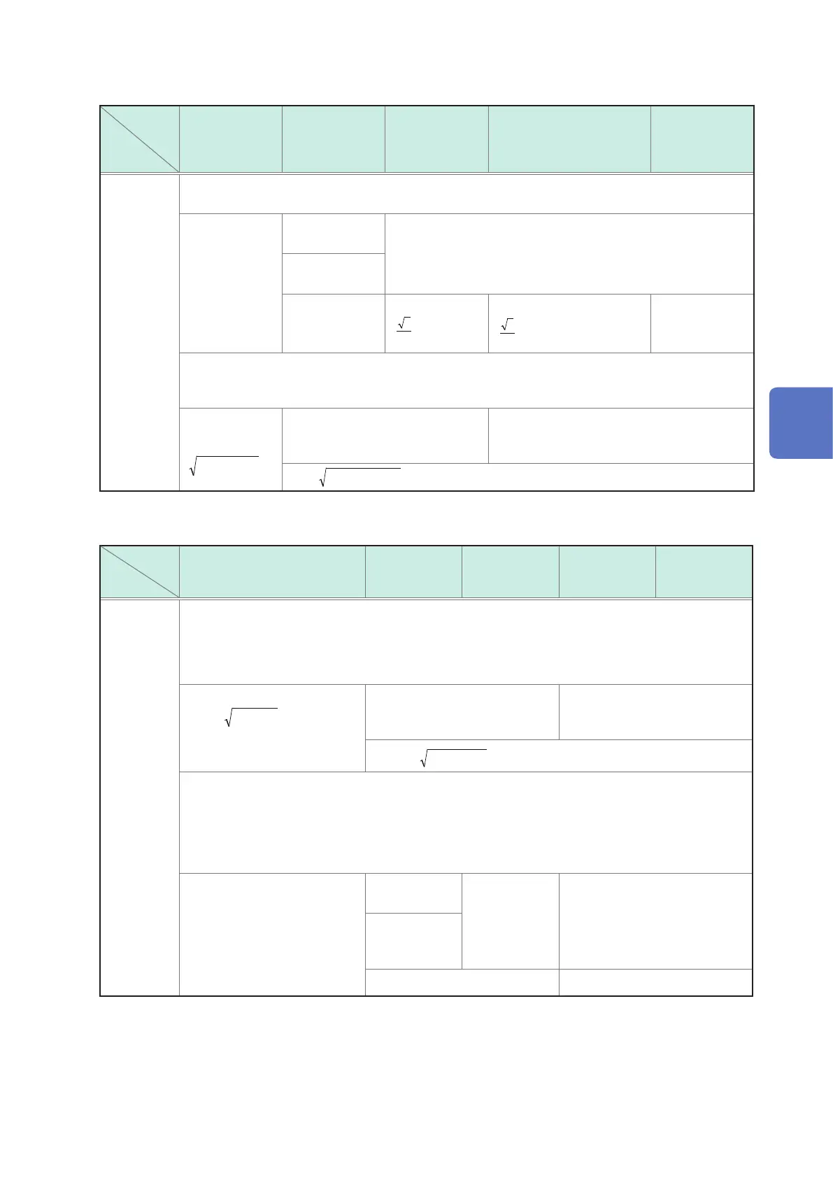
6. Apparent power (S)
Wiring
Item
Single phase
2-wire
1P2W
Single phase
3-wire
1P3W
3-phase 3-wire
3P3W2M
3-phase 3-wire
3P3W3M
3-phase 4-wire
3P4W
S [VA] PF/Q/S calculation selection: RMS value calculation
•
S
1
,
S
2
and
S
3
of 3P3W3M uses phase voltage, while
S
sum
uses line voltage.
S
1
S
c
=U
c
×I
c
S
1
S
2
S
1
S
2
S
3
During 1P3W1U
U
2
=U
1
S
sum
=S
1
+S
2
S
sum
=
( )
321
3
3
SSS ++
S
sum
=
( )
331223112
3
3
IUIUIU ×+×+×
S
sum
=S
1
+S
2
+S
3
PF/Q/S calculation selection: fundamental wave calculation
• This apparent power
S
is dened as the fundamental wave apparent power.
• (1): Harmonic calculation fundamental wave (1st order)
S
1
S
c
=
2
)1(
2
)1( cc
QP +
S
1
S
2
S
1
S
2
S
3
S
sum
=
2
)1(
2
)1( su msum
QP +
c
: Measurement channel
7. Reactive power (Q)
Wiring
Item
Single phase 2-wire
1P2W
Single phase
3-wire
1P3W
3-phase 3-wire
3P3W2M
3-phase 3-wire
3P3W3M
3-phase 4-wire
3P4W
Q [var] PF/Q/S calculation selection: RMS value calculation
• When
S < |P|
due to the effects of measurement errors or unbalance,
S = |P|
and
Q = 0
.
• Si: indicates lag and lead. The sign of reactive power Q (fundamental wave reactive power) is used.
Sign +: lag
Sign −: lead
Q
1
Q
c
=
22
cc
PSSi −
Q
1
Q
2
Q
1
Q
2
Q
3
Q
sum
=
22
sumsum
PSSi −
PF/Q/S calculation selection: Fundamental wave calculation
• This reactive power Q is dened as the fundamental wave reactive power.
• (1): Harmonic calculation fundamental wave (1st order)
•
r
: resistance after FFT,
i
: reactance after FFT
• Sign +: lag
Sign −: lead
Q
1
Q
c
=
rcicicrc
IUIU
)1()1()1()1(
×+×−
Q
1
Q
2
Q
1
Q
2
Q
1
Q
2
Q
3
During
1P3W1U
U
2
=−U
1
Q
sum
=Q
1
+Q
2
Q
sum
=Q
1
+Q
2
+Q
3
c
: Measurement channel
14
Specications

 Loading...


