68
Integrating Current and Power
Precautions when starting and stopping integration and resetting integrated
values
• Integration will stop automatically when the integration time reaches 9999 h 59 min. 59 s.
• Starting and stopping of integration and resetting of integrated values performed using
the instrument’s control keys or external control aect all parameters being integrated in
synchronization.
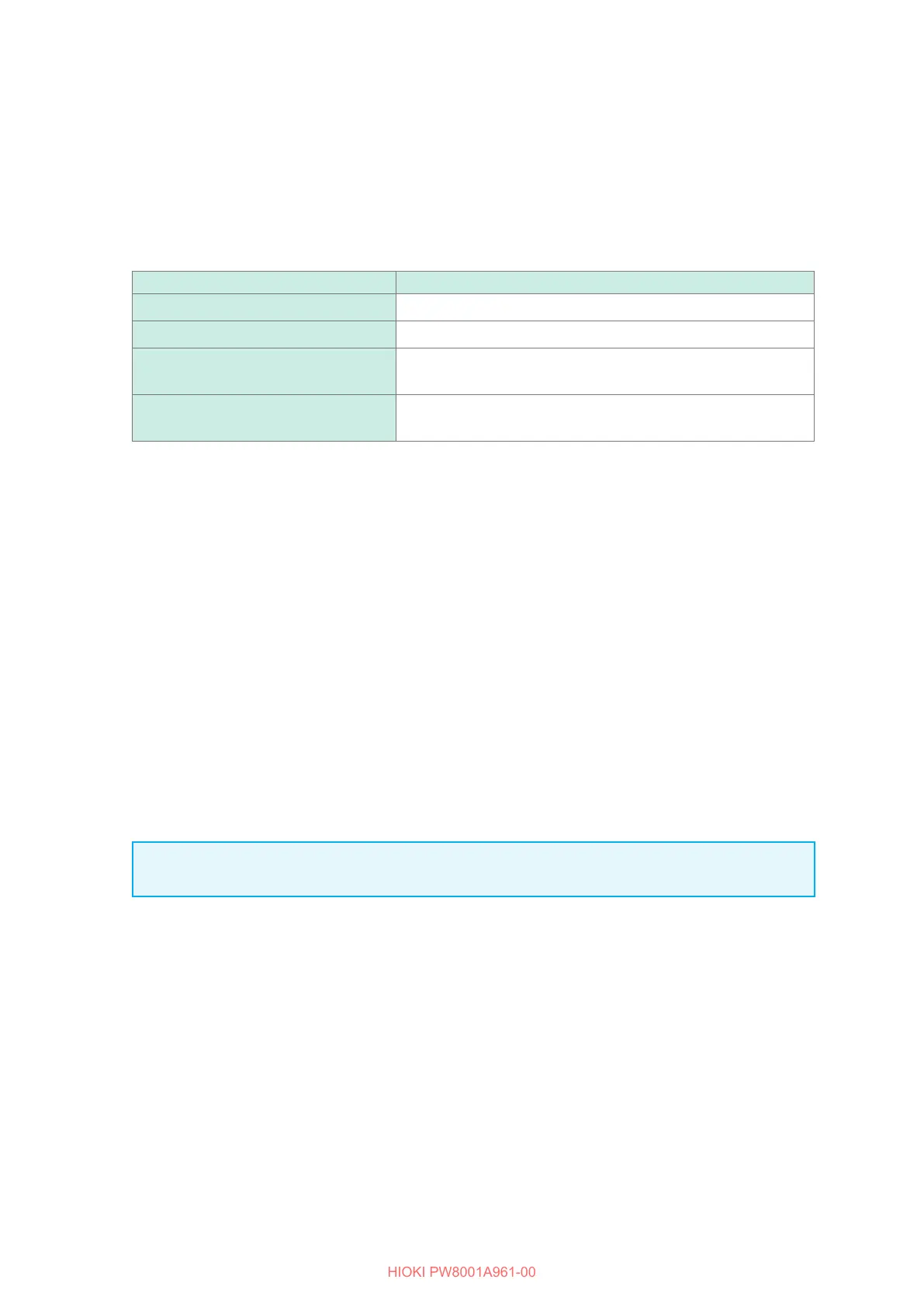
• The following parameters can be integrated depending on the wiring mode and integration mode:
Mode Parameters that can be integrated
1P2W, DC mode Ih+, Ih−, Ih, WP+, WP−, WP
1P2W Ih, WP+, WP-, WP
1P3W, 3P3W2M
(When using Ch. 1, Ch. 2)
Ih1, Ih2, WP12+, WP12−, WP12
3V3A, 3P3W3M, 3P4W
(When using Ch. 1, Ch. 2, Ch. 3)
Ih1, Ih2, Ih3, WP123+, WP123−, WP123
• Calculation results from each channel are integrated at the data refresh intervals. Consequently,
integrated values may dier from those of an instrument whose response speed, sampling speed,
or calculation methods dier.
• In current integration, the instantaneous current values are integrated when the integration mode
is DC mode, and RMS values are integrated when the integration mode is RMS mode.
• In power integration, the instantaneous power values are integrated when the integration mode is
DC mode, and active power values are integrated when the integration mode is RMS mode.
• While integration is being performed (including when the instrument is in standby mode during
real time control integration), the instrument will not accept any settings changes other than
screen changes, hold/peak hold function operation, and range changes.
• Even when the display is held during hold operation, integration operation continues internally.
However, displayed data are output as the D/A output.
• The integration display is not aected by peak hold operation.
• If a power outage occurs during integration, integrated values will be reset, and integration
operation will stop.
IMPORTANT
No data is integrated while the ranges are being switched manually or automatically.

 Loading...


