87
Motor Measurement (Motor Analysis-Equipped Model)
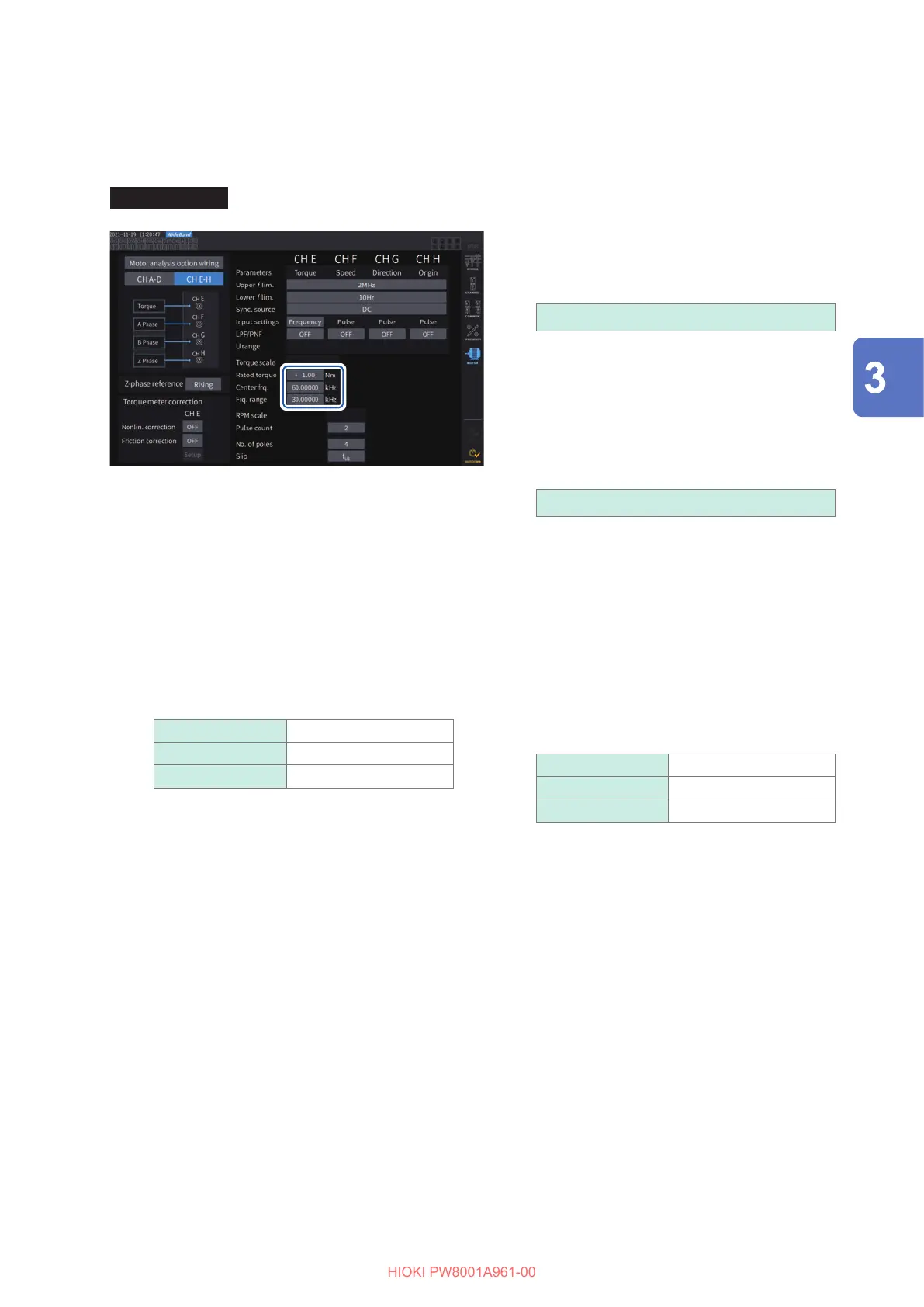
When [Frequency] is selected
When the torque input is set to [Frequency], set the scale value and unit of measurement together
in [Rated torque], [Center freq.], and [Frq. range] according to the sensor.
Display screen [INPUT] > [MOTOR]
[Rated torque]
Enter the rated torque of the torque sensor to
be connected.
±
0.01m to 9999.99k
[Center frq.], [Frq. range]
Enter the center frequency corresponding to a
torque value of zero in the [Center frq.] box.
Enter the dierence between the frequency
corresponding to the sensor rated torque and
the center frequency in the [Frq. range] box.
1.000000 kHz to 500.0000 kHz
The settings must satisfy the following
constraints:
• The center frequency plus the frequency
range is less than or equal to 500 kHz.
• The center frequency minus the frequency
range is more than or equal to 1 kHz.
Example 1: For a torque sensor with a rated torque of
500 N
m and output of 60 kHz
±
20 kHz
Rated torque 500.00
Center Frq. 60.00000
Frq. range 20.00000
Example 2: For a torque sensor with a rated
torque of 2 kN
m, positive rated torque
of 15 kHz, and negative rated torque of
5 kHz
Rated torque 2.00 k
Center Frq. 10.00000
Frq. range 5.000000
Displaying Power Numerically

 Loading...


