86
Motor Measurement (Motor Analysis-Equipped Model)
Setting the torque input
Select the type of signal used by the torque sensor connected to the instrument.
Analog For sensors that output a DC voltage signal proportional to the torque
Frequency For sensors that output a frequency signal proportional to the torque
The setting parameters vary with the selected input setting as follows.
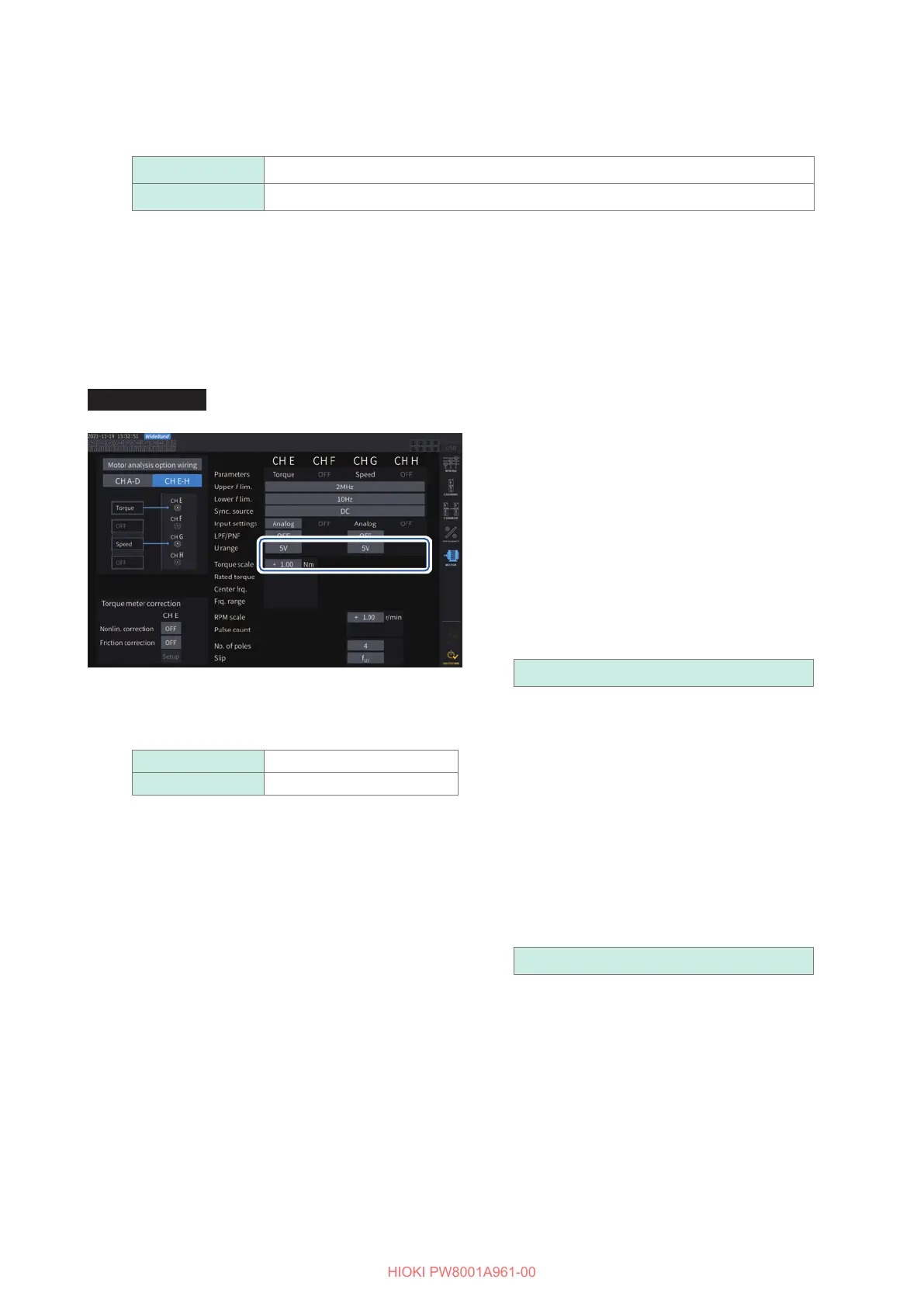
When [Analog] is selected
When the torque input is set to [Analog], set the scale value and unit together in [U range] and
[Torque scale] according to the sensor.
Display screen [INPUT] > [MOTOR]
[U range]
Select a voltage range according to the output
voltage of the torque sensor to be connected.
When the A-D or D-E channel indicator is lit up,
you can use the range keys to select a voltage
range.
When A-D is lit up, the U RANGE key functions
for Ch. A; the I RANGE key functions for
Ch. C.
When E-H is lit up, the U RANGE key
functions for Ch. E; the I RANGE key functions
for Ch. G.
1 V, 5 V, 10 V
[Torque scale]
Enter the scaling value using the numeric
keypad window.
Measured torque values are displayed as the
result of multiplying the input voltage by the
scaling value. Set the torque value per 1 V of
output from the connected torque sensor in
conjunction with the unit-of-torque setting.
([Scaling value] = [Torque sensor rated torque
value] / [Output full-scale voltage value])
In the example, the scaling value would be 50.
(50 = 500 N
m / 10)
−9999.99 to −0.01, 0.01 to 9999.99
Example: For a torque sensor with a rated torque of
500 N
m and an output scale of
±
10 V
U range 10 V
Torque scale 50.00

 Loading...


