ECC800 Data Center Controller
User Manual (for ECC800-Pro)
Copyright © Huawei Technologies Co., Ltd.
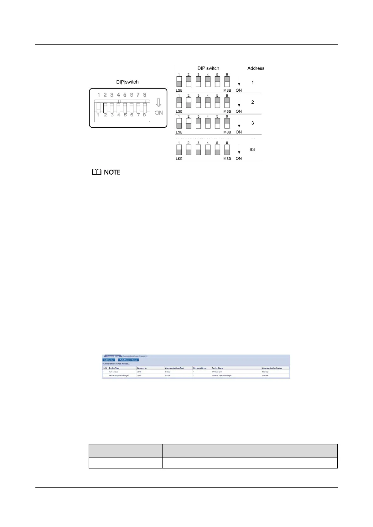
Figure 6-58 T/H sensor DIP switch
In the smart module view on the ECC800-Pro WebUI, cabinets are arranged from left to right and
from top to bottom according to T/H sensor addresses 1 to 8.
Each COM port on the UIM20A expansion module allows a maximum of eight T/H sensors to be
cascaded. Each UIM20A expansion module supports a maximum of 32 T/H sensors.
The addresses of the T/H sensors connected to the same COM port must be different. Addresses 1 to
8 are supported. The addresses of T/H sensors connected to different COM ports can be the same. In
actual configuration, bind sensors to the corresponding cabinets in sequence.
If the number of IT cabinets connected to the smart module is greater than 32, two user interface
modules are required. A UIM20A expansion module must be placed in the first cabinet of the
corresponding IT cabinets. Then the remaining cabinets need to be installed in sequence. The cable
connection principles are the same.
Set the T/H sensor addresses onsite based on the layout in the smart module view.
Step 2 Add the T/H sensor.
1. Log in to the ECC800-Pro WebUI as an administrator.
2. Add the T/H sensor.
Choose System Settings > Device Management and click Auto Discover Device to add
the T/H sensor. The device connection information is displayed.
Figure 6-59 Device connection
Step 3 Bind the T/H sensor to the cabinet referring to 6.3 Commissioning a UIM20A Expansion
Module.
Step 4 Check functions of the T/H sensor.
Table 6-43 Function check
Choose Monitoring > Cabinet > IT Cabinet n > T/H Sensor