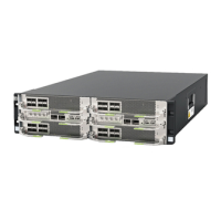
ECC800 Data Center Controller
User Manual (for ECC800-Pro)
Copyright © Huawei Technologies Co., Ltd.
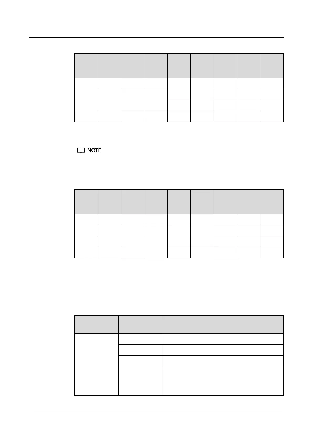
Table 8-1 Setting a device address
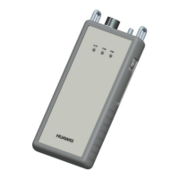
Set monitoring parameters for the UPS2000-G-(6 kVA–20 kVA).
Operate the DIP switch S2 on the optional Modbus card to set the UPS2000-G device address. Toggle
switches 1 to 8 of DIP switch S2 specify the device address in binary mode. ON indicates 0, and OFF
indicates 1.
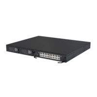
Table 8-2 Setting a device address
Step 2 Add a UPS2000-G.
1. Log in to the ECC800-Pro WebUI as an administrator.
2. Add a UPS2000-G.
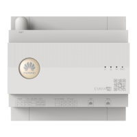
Table 8-3 Adding a UPS2000-G
Choose System
Settings >
Device
Management
and click Add
Device. The
parameters for
adding devices
are displayed.
Select UPS from the drop-down list box.
Select UPS2000G-A from the drop-down list box.
Select ECC800 from the drop-down list box.
Select COM2 from the drop-down list box.
NOTE
The setting example indicates that the UPS2000-G is
connected to the COM2 port on the ECC800-Pro. If the