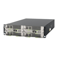
ECC800 Data Center Controller
User Manual (for ECC800-Pro)
Copyright © Huawei Technologies Co., Ltd.
COM7/AIDI_7 and COM8/AIDI_8 form a group).
The 12 V DC power supply can be switched on or off and is on
by default.
Connects to the ECC800-Pro through the POE port.
One 4-bit DIP switch is used to set the RS485 address.
OFF indicates 0 and ON indicates 1.
Bit 1 is the least significant bit, and bit 4 is the most significant
bit. For example, if the board address is 5, the corresponding
bits are ON, OFF, ON, and OFF, and the corresponding binary
number is 1010 (ON is 1 and OFF is 0).
Communications Port
The following table describes the pin assignment for ports COM1/AIDI_1 to COM8/AIDI_8.
Table 3-19 Pin assignment for ports COM1/AIDI_1 to COM8/AIDI_8
The following table describes the pin assignments for the COM_IN and COM_OUT ports.
Table 3-20 Pin assignment for the COM_IN and COM_OUT ports
12 V (input power, supplying power to the module)