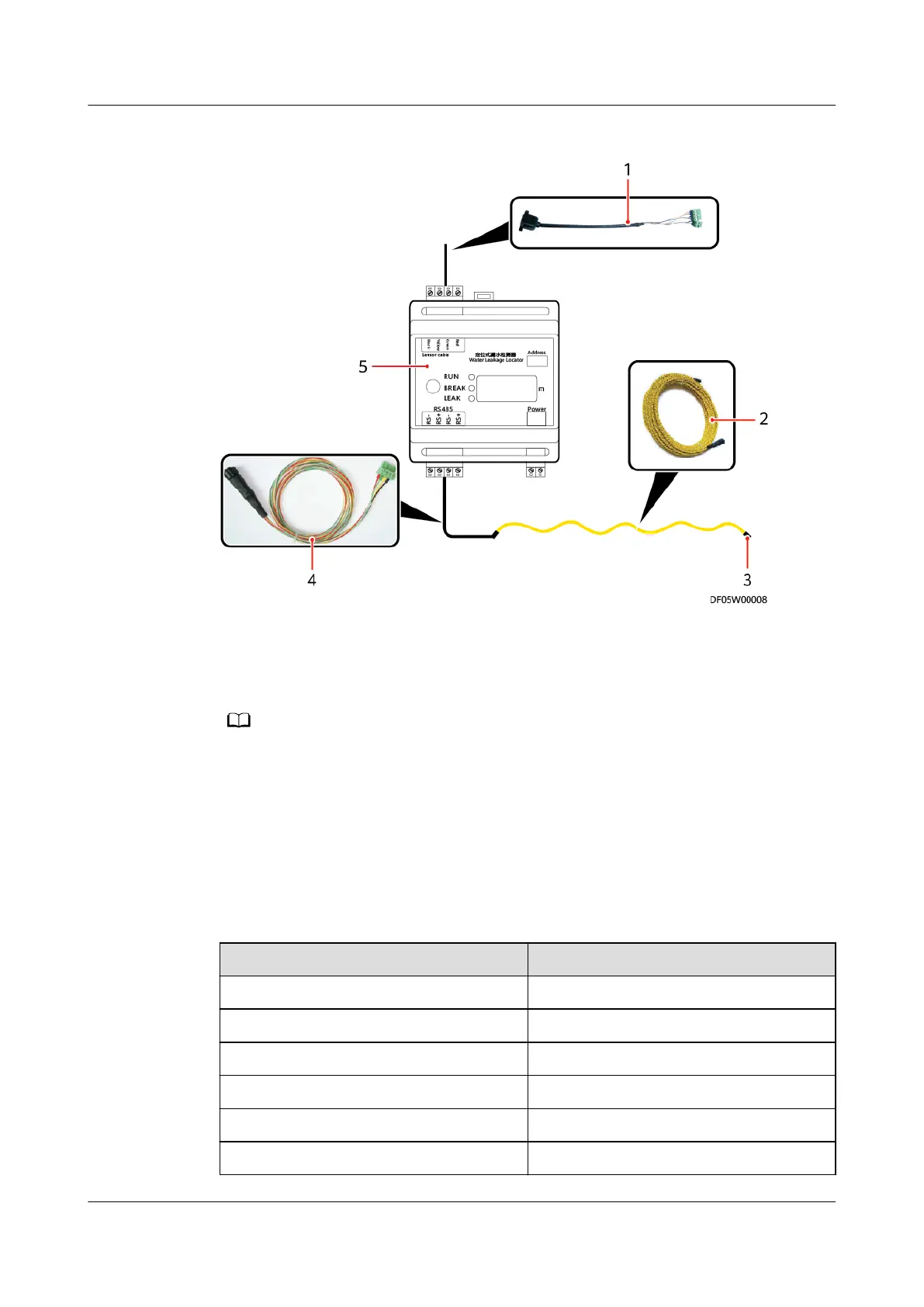
Figure 3-35 Connection diagram for location-type water sensor components
(1) Tie line (2) Water leakage location
cable
(3) Terminal
(4) Extension line (5) Water leakage locator
● Two types (A and B) of end caps are delivered in early stage. The site may support only
one type. In the later delivery, there is only one type supported, that is, type A and type
B are not distinguished any more.
● If there are two types (A and B) delivered with the product, select either of the types to
complete cable connection. After the cable is connected and the water leakage locator
is powered on and initialized, if the buzzer keeps buzzing and the alarm location is a
stable value that is greater than the total length of the water leakage location cable,
replace the end cap with the other end cap.
Table 3-2 RJ45 cable wire sequence of the Tie line
Pin
Denition
Pin 1 (orange-and-white) RS485+
Pin 2 (orange) RS485-
Pin 3 (green-and-white) 12VDC
Pin 4 (blue) RS485+
Pin 5 (blue-and-white) RS485-
Pin 6 (green) -
iMaster NetEco
Device Installation and Commissioning Guide (Data
Center) 3 Installing Devices
Issue 02 (2021-05-12) Copyright © Huawei Technologies Co., Ltd. 41
 Loading...