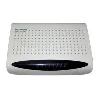
(4) RJ11 analog audio port (5) RS232 standard serial port
Procedure
Step 1 Use cable ties to bind the GSM modem to the mounting bar near the server
installation position on the rear door of the network cabinet.
Step 2 Insert a SIM card into the 4G SMS modem.
Use a tool such as the small screwdriver to press the yellow key. Put the SIM card
on the ejected tray, and insert the tray into the SMS modem.
Step 3 Connect the antenna to the antenna connector.
Step 4 Connect the serial cable.
Connect one end of the serial cable to the modem, and the other end to the
transfer cable. Connect the other end of the transfer cable to an idle serial port on
the server. For details about the serial ports on the server, see Server Ports.
Use the connector convertor delivered with the SMS modem if the connector of the serial
cable does not match the serial port on the server.
Step 5 Connect the power cable.
1. Connect one end of the USB cable to the USB 2.0 port on the modem.
2. Connect the other end of the power adapter to the universal conversion C1
socket.
3. Connect the other end of the universal conversion C1 socket to the rPDU
through a transfer cable (C13/C14 cable or China standard C13 cable).
After the power cable is connected, turn on the power supply. The modem
indicator should blink regularly. Table 4-4 describes the relationships between the
indicator status and the modem status.
Table 4-4 Relationships between the indicator status and the modem status
Indicator Status
Modem Status
On
The modem is searching for a network or
a call is set up.
Blinks at intervals of 800 ms The modem is connected to the network.
Blinks at intervals of 200 ms The modem is transmitting data.
O The modem is powered o.
For details about how to connect the modem, see the product manual delivered with the
modem.
iMaster NetEco
Device Installation and Commissioning Guide (Data
Center) 4 Connecting Monitoring Cables to Devices
Issue 02 (2021-05-12) Copyright © Huawei Technologies Co., Ltd. 72
 Loading...