17-19 Operators’ Manual
990400 Rev C 2010 May 1
9-4
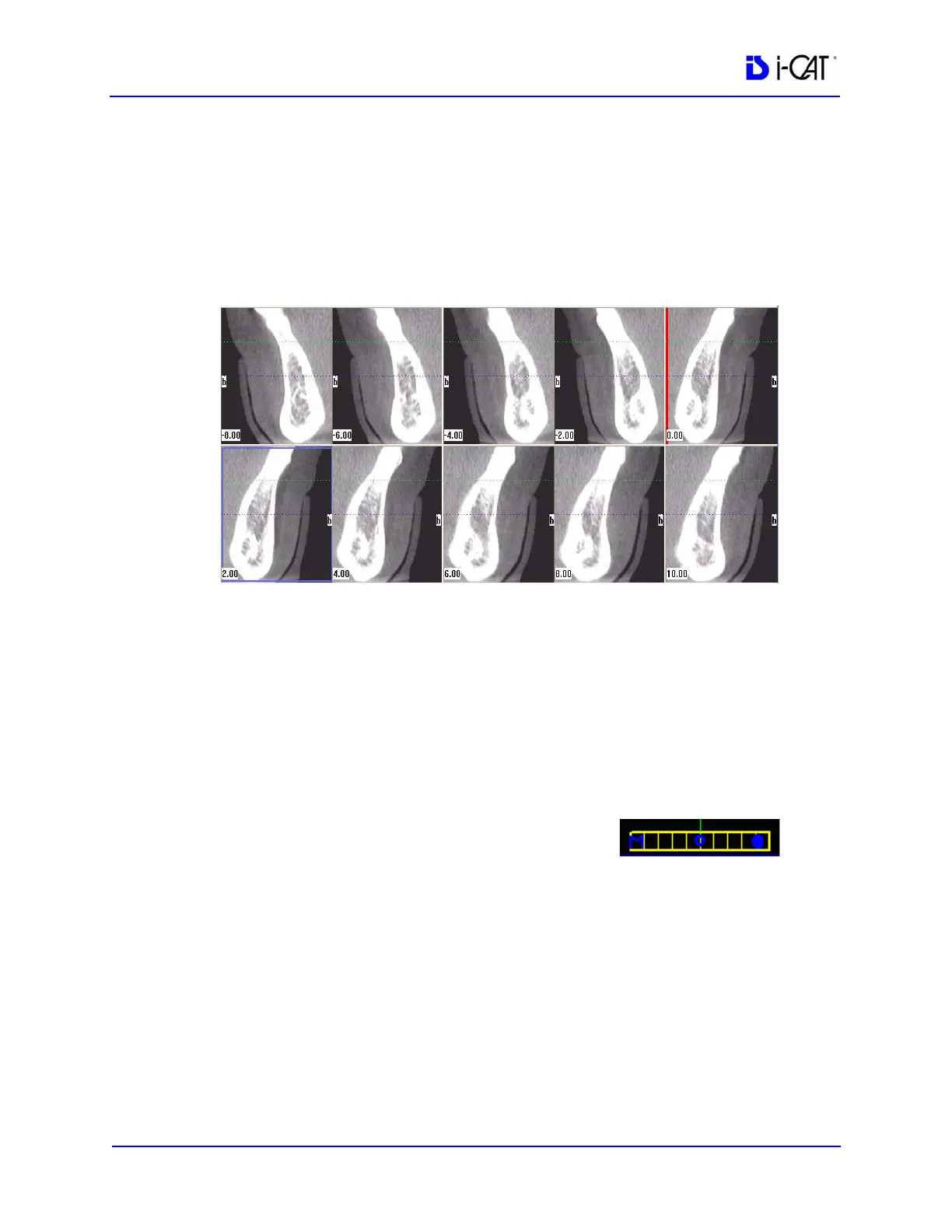
The blue hash mark represents the center line of the axial slices
displayed on the cross section views. (The corresponding center
cross section slice is displayed with a blue frame in the cross section
views.) The orange hash marks represent the other axial slices
displayed on the cross section views. At the top of the axial slice
position view, the positions of the rightmost axial cross section,
center cross section, and leftmost cross section are displayed.
The cross section views are located as indicated by the hash marks
displayed in the axial slice position view. If the 0.00 position is
displayed, it is outlined in red. All slices to the patient’s right side
are displayed as negative numbers. All slices to the patient’s left side
are displayed as positive numbers.
2. Use the panoramic map view to modify the position of the cross
section views (which are represented on the axial slice position
view) and modify the criteria used to generate the cross section
views (at the lower right of the Implant Planning Screen):
a. Drag the O in the center of the
horizontal slice control (bottom of
view) left or right to change the
location of the center axial cross section. Changes made
here are reflected on the axial slice position view and the
cross section views.
b. Drag the solid dot on the right side of the diagonal slice
control (bottom right) to adjust the slice thickness displayed
on the panoramic map view.