BIOS Initialization Intel® Server System S7000FC4UR
Revision 1.0
118
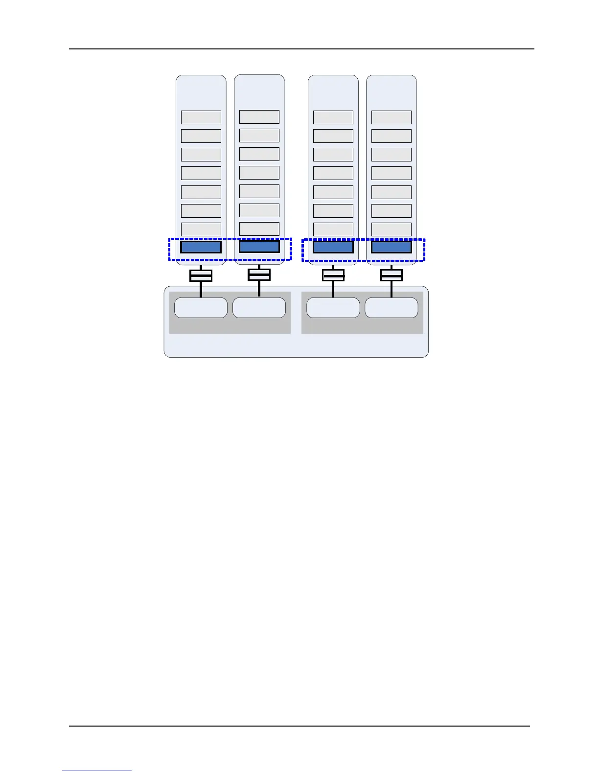
Figure 39. Memory Population for Dual-Channel Configuration on Both Branches
This configuration:
Minimal dual-channel, dual branch configuration is one lock-step FBDIMM pair in the
DIMM_1 socket on Memory Riser Boards A and B and an additional lock-step FBDIMM
pair in the DIMM_1 socket on Memory Riser Boards C and D. Additional lock-step pairs
can be populated to increase system memory as desired.
Provides the highest system performance because using both memory branches
doubles FBDIMM bandwidth.
FBDIMM lock-stepped pair in identically numbered DIMM slots on both memory riser
boards on a branch must be identical in organization, size, and speed for dual-channel
operation.
FBDIMM lock-stepped pairs in identically numbered DIMM slots do not have to be
identical between branches. However, this is recommended to improve memory
performance.
The BIOS enables all installed FBDIMM modules and configures the system for dual-
channel mode.
Intel® Chipset
Memory Controller Hub
Branch 0
Channel 0
Channel 1
Branch 1
Channel 2 Channel 3
DIMM 1
DIMM 2
DIMM 3
DIMM 4
DIMM 5
DIMM 6
DIMM 8
Memory
Rise
DIMM 7
DIMM 1
DIMM 2
DIMM 3
DIMM 4
DIMM 5
DIMM 6
DIMM 8
Memory
Rise
B
DIMM 7
Lock - step pair
Branch 0
DIMM 1
DIMM
2
DIMM 3
DIMM 4
DIMM 5
DIMM 6
DIMM 8
Memory
Riser
C
DIMM 7
DIMM 1
DIMM 2
DIMM 3
DIMM 4
DIMM 5
DIMM 6
DIMM 8
Memory
Riser
D
DIMM
7
Lock - step pai
Branch 1

 Loading...


