BIOS Initialization Intel® Server System S7000FC4UR
Revision 1.0
116
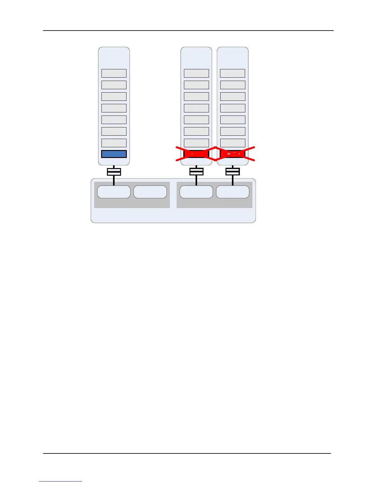
Figure 37. Memory Population for Single-Channel Failsafe
This configuration:
The population in Branch 0 meets the requirements for single-channel mode only.
The population in Branch 1 meets the requirements for dual-channel mode because the
FBDIMMs installed in the DIMM_1 sockets on Memory Riser Boards C and D are
identical in terms of organization, speed, and size.
The BIOS uses the FBDIMM population of Slot 1 on both Memory Riser Board A and B
(Branch 0) to determine the memory-operating mode. Therefore, the BIOS disables all
FBDIMMs except Memory Riser Board A, DIMM_1 and configures the system for single-
channel mode.
Intel® Chipset
Memory Controller Hub
Branch 0
Channel 0 Channel 1
Branch 1
Channel 2 Channel 3
DIMM 1
DIMM 2
DIMM 3
DIMM 4
DIMM 5
DIMM 6
DIMM 8
Memory
Rise
DIMM 7
DIMM 1
DIMM 2
DIMM 3
DIMM 4
DIMM 5
DIMM 6
DIMM 8
Memory
Rise
C
DIMM 7
DIMM 1
DIMM 2
DIMM
3
DIMM
4
DIMM 5
DIMM 6
DIMM 8
Memory
Riser
D
DIMM 7
Disabled

 Loading...


