Intel® Server System S7000FC4UR TPS Main Board
Revision 1.0
19
0 1 0 0 4
0 1 0 1 5
0 1 1 0 6
0 1 1 1 7
1 0 0 0 8
1 0 0 1 9
1 0 1 0 A
1 0 1 1 B
1 1 0 0 C
1 1 0 1 D
1 1 1 0 E
1 1 1 1 F
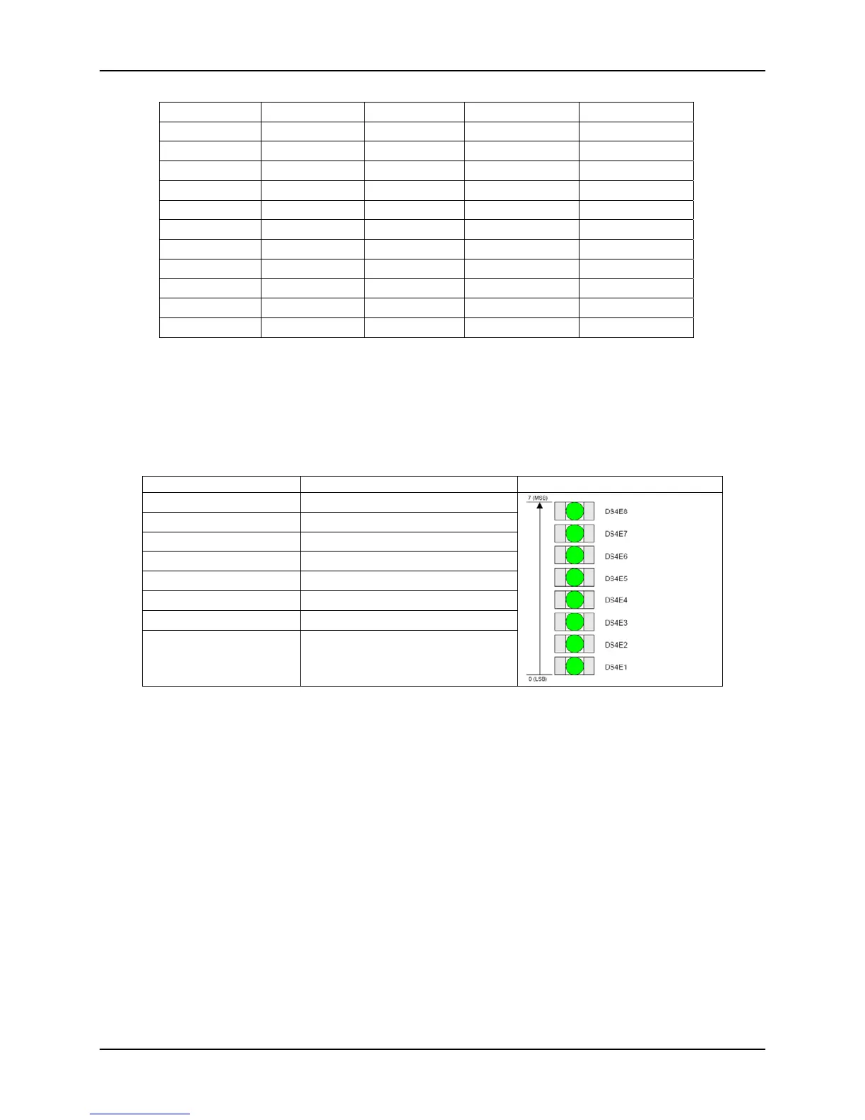
The Post LEDs are situated as shown in the below table along with the corresponding reference
designators.
Table 7. POST Code LED Definition
Post Code Bit LED Reference Designator POST Code LEDs
7 (MSB) DS4E8
6 DS4E7
5 DS4E6
4 DS4E5
3 DS4E4
2 DS4E3
1 DS4E2
0 (LSB) DS4E1
2.2.18 Programmable Logic Devices (PLDs)
The main board has two Programmable Logic Devices (PLDs) for fundamental logic on the main
board. Due to the nature of these devices, they are not programmable by an end user.
2.2.18.1 Powergood / Reset
Powergood / Reset: The main board pwren / pwrgd chain begins with logic which checks for
both power supplies’ presence and power-ok input assertions. Based on these signals,
PS_PWROK will assert to start the VR chain on the main board. (See Figure 5 for the VR
sequence.)
Upon assertion of the P1V5_PWRGD signal, VTT_PWREN signal will enable the VTT
VR. VTT_PWRGD_3_3V signal from VTT VR to the PLD will enable the
CPU#_VR_PWREN to all regulators of populated CPUs.

 Loading...


