Intel® Server System S7000FC4UR TPS BIOS Initialization
Revision 1.0
109
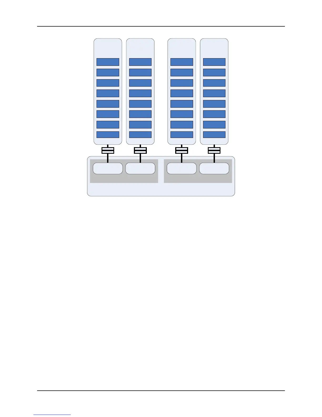
Figure 33. Memory Subsystem Layout
14.2.2 Memory Population Table
The following table describes the memory configurations that are fully supported by the BIOS.
The system may work in other configurations, but the behavior may be unpredictable or
abnormal. These notations are used in the table:
SC: Single-channel mode
SCn: Single-channel mode with n FBDIMMs
DCm_ABCD): Dual-channel mode with m FBDIMMs per channel, and boards A, B, C, or
D populated
M: Memory Mirroring is possible
S: DIMM Sparing is possible
×: Not possible for RAS mode, or not present for the memory riser board
Intel® Chipset
Memory Controller Hub
Branch 0
Channel 0
Channel 1
Branch 1
Channel 2 Channel 3
DIMM 1
DIMM 2
DIMM 3
DIMM 4
DIMM 5
DIMM 6
DIMM 8
Memory
Rise
DIMM 7
DIMM 1
DIMM 2
DIMM 3
DIMM 4
DIMM 5
DIMM 6
DIMM 8
Memory
Rise
B
DIMM 7
DIMM 1
DIMM 2
DIMM 3
DIMM 4
DIMM 5
DIMM 6
DIMM 8
Memory
Rise
C
DIMM 7
DIMM 1
DIMM 2
DIMM 3
DIMM 4
DIMM 5
DIMM 6
DIMM 8
Memory
Rise
D
DIMM 7

 Loading...


