Main Board Server Management Intel® Server System S7000FC4UR TPS
Revision 1.0
Intel order number E18291-001
40
PECI uses a single wire for wake-up, self-clocking and data transfer. No additional control
signals are required. Each bit transferred will begin with a driven, rising edge from an idle level
near zero volts. The duration of the signal driven high depends on whether the bit value is a
logic “0” or logic “1”. PECI also includes variable transfer rate established with every message.
Further details on the bus implementation are available in the Platform Environment Control
Interface (PECI) Specification. The details are as follows:
Electrical requirements
Platform topologies
Power management state handling
Bus device enumeration, commands
Address values
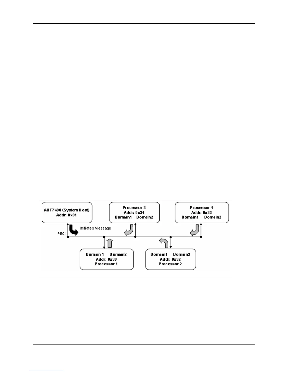
The PECI architecture includes system host and client devices. A system host, represented in
main board by the ADT7490*, is a special device with specific bus management duties.
Only one system host is allowed on a PECI physical layer and this device initiates all
transactions. Client devices, represented by processors, are any other devices connected to
PECI in the system that are not the system host. The main board PECI physical layer topology
supports a 4-way symmetric multi-processor system. PECI devices are identified by their
unique, fixed address.
All processor PECI devices are located in the address range of 0x30 to 0x33. Figure 11
provides an example implementation.
Figure 11. Main Board PECI Physical Layer Topology
 Loading...


