Intel® Server System S7000FC4UR TPS BIOS Initialization
Revision 1.0
119
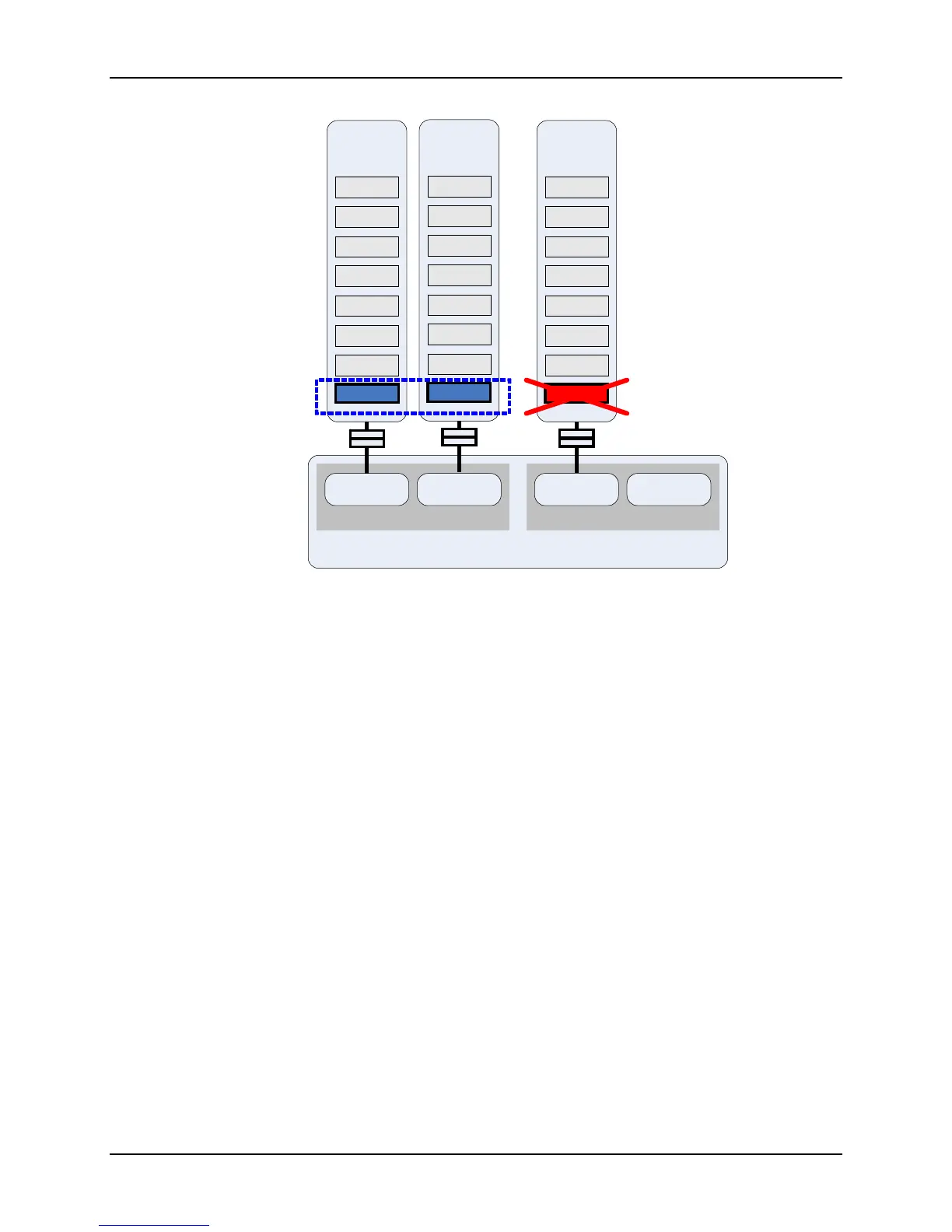
Figure 40. Memory Population for Dual-Channel Failsafe
This configuration:
The population in Branch 0 meets the requirements for dual-channel mode because the
FBDIMMs installed in the DIMM_1 sockets on Memory Riser Boards A and B are
identical in terms of organization, speed, and size.
The population in Branch 1 does not meet the requirements for dual-channel mode
because only Memory Riser Board C, DIMM_1 is installed.
The BIOS uses the FBDIMM population of Slot 1 on both Memory Riser Board A and B
(Branch 0) to determine the memory-operating mode.
The BIOS configures the system for dual-channel mode on one branch and disables
Branch 1.
14.2.5 DIMM Sparing Population Rules
FBDIMM Sparing relies on dedicating the largest available FBDIMM rank as a spare in the
event of a pending FBDIMM failure. Sparing is only supported in dual channel mode and
requires a minimum of two lock-stepped ranks of memory. This requires either two lock-stepped
pairs of single-ranked FBDIMM modules or one lock-stepped pair of dual ranked FBDIMM
modules. The chipset supports FBDIMM Sparing on each branch independently.
Intel® Chipset
Memory Controller Hub
Branch 0
Channel 0 Channel 1
Branch 1
Channel 2 Channel 3
DIMM 1
DIMM 2
DIMM 3
DIMM 4
DIMM 5
DIMM 6
DIMM 8
Memory
Rise
DIMM 7
DIMM 1
DIMM 2
DIMM 3
DIMM 4
DIMM 5
DIMM 6
DIMM 8
Memory
Riser
B
DIMM 7
Lock - step pai
Branch 0
DIMM 1
DIMM 2
DIMM 3
DIMM 4
DIMM 5
DIMM 6
DIMM 8
Memory
Rise
C
DIMM 7
Disabled

 Loading...


