SAS Backplane Intel® Server System S7000FC4UR
Revision 1.0
66
7.3.9.8 I
2
C* Addresses
Two I
2
C* devices and their addresses are listed in Table 15 and one in Table 16.
Table 15. I
2
C* Local Bus Addresses
Device Address Bus Description
AT24C64* 0xAC VSC local bus Private SAS backplane FRU EEPROM
DS75* 0x90 VSC local bus Private SAS backplane temperature sensor
Table 16. Global I
2
C* bus Addresses (IPM Bus)
Device Address Bus Description
VSC410* NA IPMB system interface VSC410* controller public IPMB bus
Table 17. I
2
C* I/O Bus Addresses
Device Address Bus Description
PCA9554* 0x42 SMB_SYS_PWR_SDA/SCL Micro controller public I/O bus
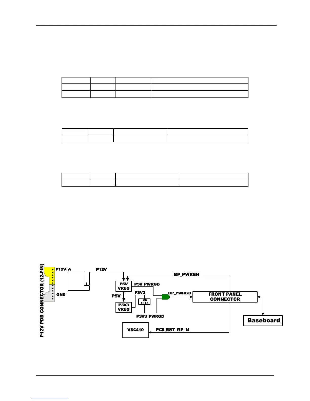
7.3.10 Resets
The principal reset for logic on the SAS backplane is supplied by the PCI_RST_BP_N signal
from the server board via the 100-pin connector
The PCA9554* device being used to control the fans, has an internal power-on reset that
configures all its I/O pins as inputs.
See the diagram below for reset flow.
Figure 17. SAS Backplane Reset and Power Good Block Diagram

 Loading...


