Intel® Server System S7000FC4UR TPS Main Board
Revision 1.0
11
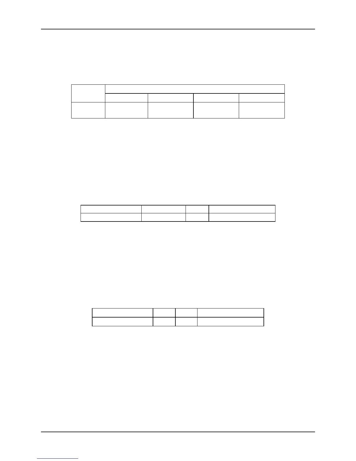
Table 3 describes how the interrupts for each of the PCI devices are mapped to the Enterprise
Southbridge 2.
Table 3. PCI Interrupt Mapping
Enterprise Southbridge 2 PCI Host Bridge
Device
INTA# INTB# INTC# INTD#
RN50 Video
Controller
INTA#
[ESB_PIRQB_N]
2.2.5.2 PCI IDSEL Signal
The IDSEL signal is used as a chip-select for PCI32 devices during read/write transactions. The
Enterprise Southbridge 2 PCI32 controller asserts a specific address bit on a given PCI bus to
toggle the IDSEL signal to the PCI device. For the main board, the address bit to IDSEL
mapping is shown in Table 4.
Table 4. IDSEL Mapping
Device Device Number IDSEL Host Bridge
RN50 Video Controller 12 AD28 Enterprise Southbridge 2
2.2.5.3 PCI Bus Arbitration Signals
Request (REQ#) signals indicate to the bus arbiter that an agent/device desires the use of the
bus. The Grant (GNT#) signal indicates to the agent/device that access to the bus has been
granted. Every master has its own REQ#, which must be tri-stated while RST# is asserted.
These are point-to-point signals, which are assigned to every bus master.
Table 5. Arbitration Connections
Device REQ# GNT# Host Bridge
RN50 Video Controller 0 0 Enterprise Southbridge 2
2.2.6 Main board Memory Interface
The main board includes four 164 pin x16 PCI-Express* connectors that interface with up to four
Memory Risers. Each of these Memory Riser connectors are individually connected to one of
the four MCH’s FBD channels.
Serial Presence Detect (SPD) side-band signals are also passed between the Memory Risers
and the Intel
®
7300 Chipset MCH.
The main board supports the following memory riser population configurations:

 Loading...


