Intel® Server System S7000FC4UR TPS BMC Functional Specifications
Revision 1.0
259
System status / fault LED
Chassis ID LED
The front panel provides the following buttons:
Reset button
Power button
System diagnostic interrupt button (NMI button)
Chassis ID button
22.6.1 Power LED
The green power LED is active when system DC power is on. The power LED reflects a
combination of the state of system (DC) power and the system ACPI state. The BIOS controls it.
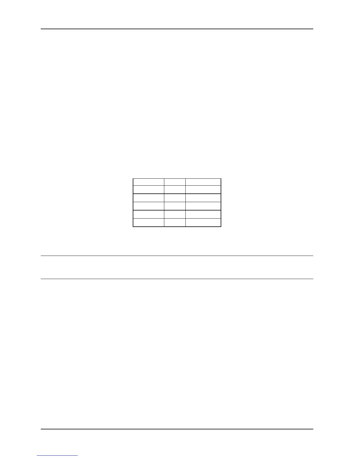
Table 97. Power LED Indicator States
State ACPI Power LED
Power off No Off
Power on No Solid on
S4 / S5 Yes Off
S1 Sleep Yes ~1 Hz blink
S0 Yes Solid on
22.6.2 System Status LED
Note: The system status LED state shows the state for the current, most severe fault. Example:
If there was a critical fault due to one source and a non-critical fault due to another source, the
system status LED state would be the state for the critical fault.
The system status / fault LED is a bicolor LED. Green (status) is used to show a normal
operation state or a degraded operation. Amber (fault) shows the platform hardware state and
over-rides the green status. The system status LED is mainly controlled by the BMC. Early in
the startup boot process, the BIOS checks the chipset for any memory errors.
The BMC-detected states are included in the LED states. For fault states that are monitored by
BMC sensors, the contribution to the LED state follows the associated sensor state, with priority
given to the most critical asserted state.
When the server is powered down (transitions to the DC-off state or S5), the BMC is still on
standby power and retains the sensor and front panel status LED state established before the
power-down event.
Note: System status LED will not update the status of the LED when the HSC events are
generated.
Table 98. System Status LED Indicator States

 Loading...


