Intel® Server System S7000FC4UR TPS System Chassis and Sub-Assemblies
Revision 1.0
79
Figure 23. Power Supply Module
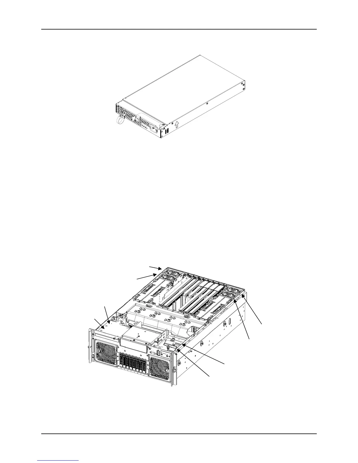
9.2.2 Fan Subsystem
Two fan assemblies are located at the front of the chassis and are removed from the front (See
Figure 9). Each assembly contains two fans. The fans are in a sheetmetal enclosure with a
plastic bezel mounted to the front. The assembly has an integrated amber LED wired to the
front of the plastic bezel. The LED will turn on when either fan is not functioning within
specifications. The fan connector extends from the rear of the fan assembly.
Four additional fans are located at the rear of the chassis and are removed from the top (See
Figure 24). The fans are assembled into a plastic enclosure. The fan has an integrated amber
LED that will turn on when the fan is not functioning within specifications. The fan connector
extends from the bottom of the fan assembly.
Figure 24. Fan Locations
System Fan 1
System Fan 2
Memory Fan 1
System Fan 4
Memory Fan 4
Memory Fan 2
Memory Fan 3
System Fan 3

 Loading...


