61
11 Parameterization
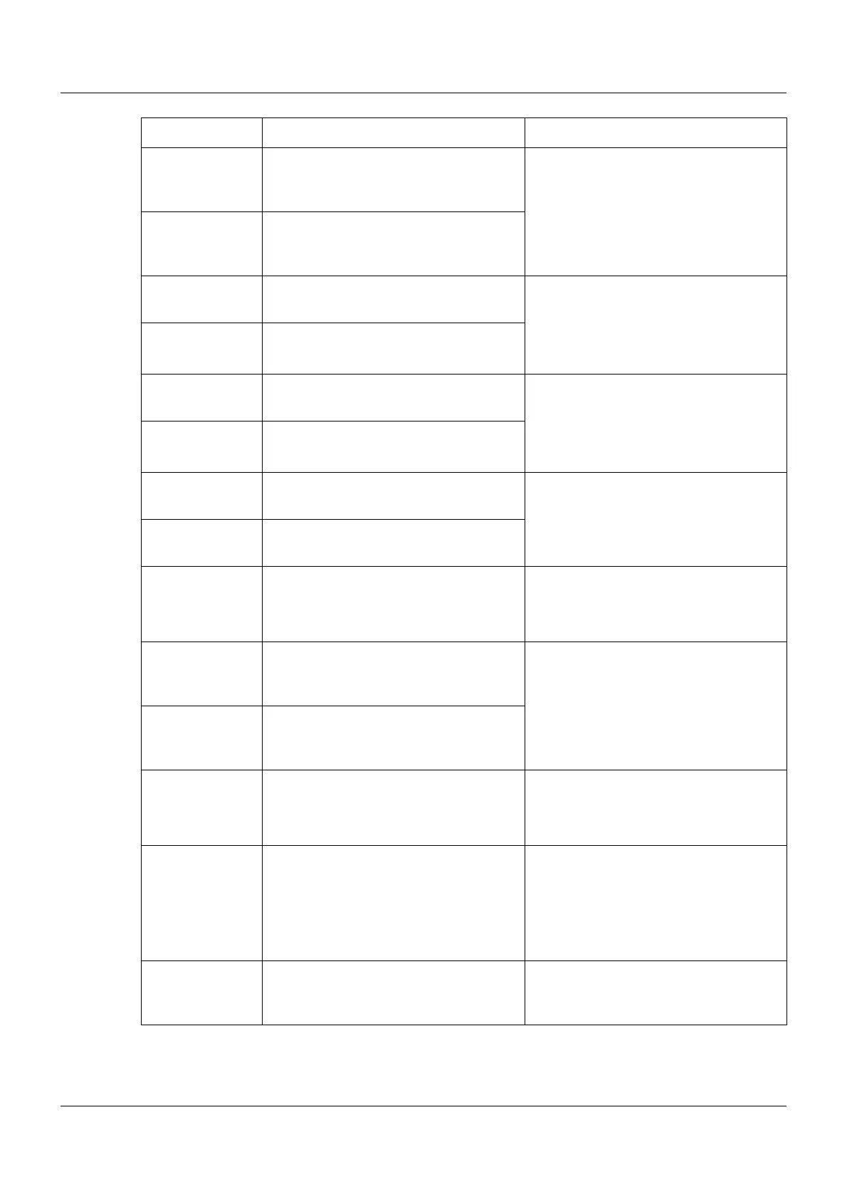
Parameter Setting Description
Proportional band
1
(Xp1)
0 to 9999 Value for the proportional band
The controller structure has no effect if
Xp = 0 (behavior identical to limit value
monitoring function)!
For a continuous controller, Xp must be
> 0.
Proportional band
2
(Xp2)
0 to 9999
Derivative time 1
(Tv1)
0 to 80 to 9999 s The derivative time influences the differ-
ential component (D component) of the
controller output signal.
The greater the derivative time, the
more effect the D component has.
Derivative time 2
(Tv2)
0 to 80 to 9999 s
Reset time 1
(Tn1)
0 to 350 to 9999 s The reset time influences the integral
component (I component) of the control-
ler output signal.
The greater the reset time, the less
effect the I component has.
Reset time 2
(Tn2)
0 to 350 to 9999 s
Cycle time 1
(Cy1)
0 to 20 to 999.9 s When using a switched output, the cycle
time should be chosen so that the
energy supply to the process is as con-
tinuous as possible, and the switching
elements are not overloaded.
Cycle time 2
(Cy2)
0 to 20 to 999.9 s
Contact spacing
(Xsh)
0 to 999.9 Spacing between the two control con-
tacts for a three-state controller, three-
step controller, and continuous control-
ler with integrated position controller
Switching differ-
ential 1
(Xd1)
0 to 1 to 999.9 Hysteresis for a switching controller with
proportional band Xp = 0
Switching differ-
ential 2
(Xd2)
0 to 1 to 999.9
Actuator time
(TT)
5 to 60 to 3000 s Control valve runtime range used for a
three-step controller and continuous
controller with integrated position con-
troller
Working point
(Y0)
-100 to 0 to +100 % Working point correction for a P or PD
controller (correction value for the output
level)
If the actual value (x) has reached the
setpoint value (w), the output level (y)
corresponds to the working point (Y0).
Max. output level
limit
(Y1)
0 to 100 % Admissible maximum output level (only
effective if Xp > 0)