69
12 Configuration
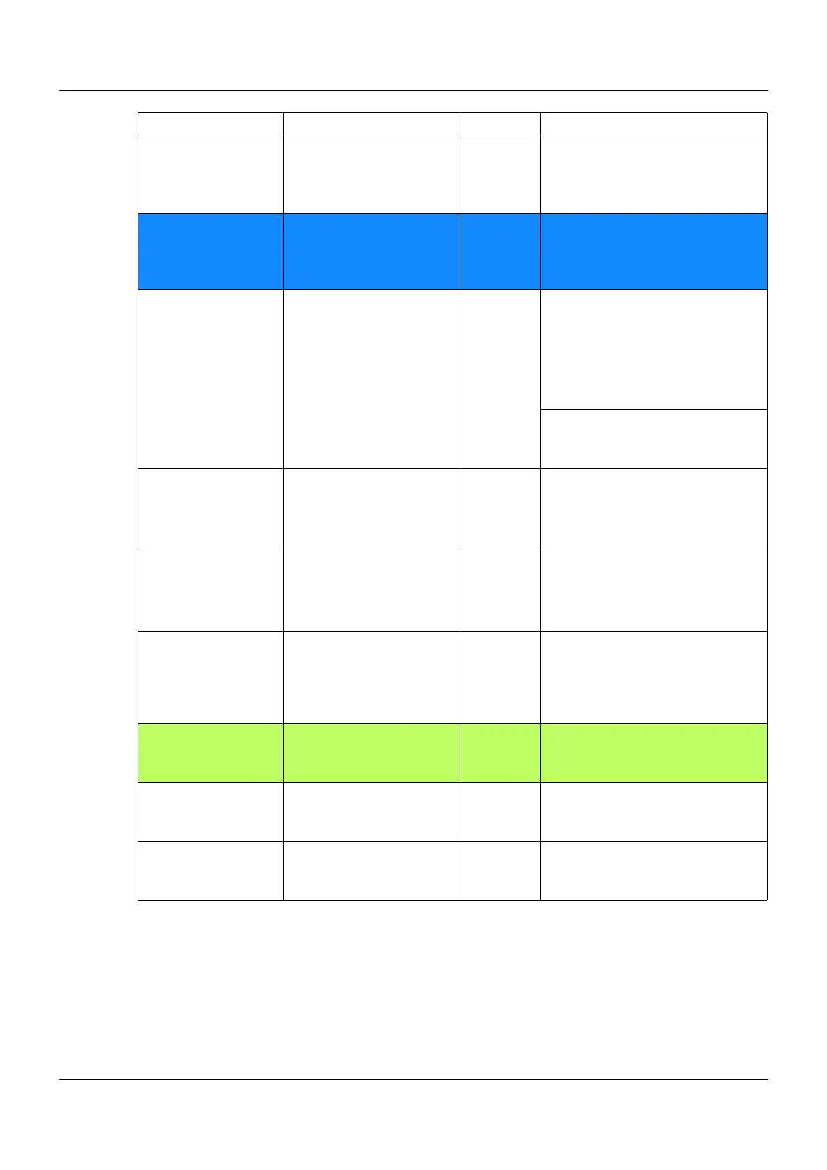
Digital control signals Digital control signals 1to8 Internal Logic level for the defined digital
control signals 1 to 8
Ö Chapter 12.14 Digital controller
signals Page 135
Limit value outputs Limit value output 1 to 16 Internal Logic level of the limit value moni-
toring function 1 to 16
Ö Chapter 12.9 Limit value moni-
toring function Page 106
Timer Timer output 1 to 4 Internal Logic level of the output signals of
timer 1 to 4
Logic level "0", function inactive
Logic level "1", function active
Ö Chapter 12.13 Timer or week-
time switch Page 132
Timer end signal 1 to 4
Timer tolerance band 1 to 4
Timer stop signal 1 to 4
Logic output Logic output 1 to 8 Internal Result of logic function 1 to 8
Ö Chapter 12.15 Math/logic Page
138
Ramp signals Ramp end signal 1 Internal Logic level "0", function inactive
Logic level "1", function active
Ö Chapter 12.6.8 Ramp function
Page 99
Tolerance band signal 1
Ramp end signal 2
Tolerance band signal 2
Program controller Program end signal Internal
Logic level "0", function inactive
Logic level "1", function active
Ö Chapter 12.12 Program control-
ler Page 123
Program auto signal
Tolerance band signal
Program stop signal
Control contacts Operating contact 1 to 16 Internal Logic level of the operating con-
tacts, for example in automatic
mode.
Ö Chapter 8.1.5 Operating con-
tacts Page 51
Flag Digital flags 1 to 8 Internal Logic level of the digital flag
Ö Chapter 12.16 Flags/service
Page 140
Service Service signal Internal
Logic level of the service signal
Ö Chapter 12.16 Flags/service
Page 140
Function buttons Function key 1 to 2 Internal
Logic level of the 2 function buttons
Ö Chapter 5.1 Display and oper-
ating concept Page 37
Category Signal Type Description