71
12 Configuration
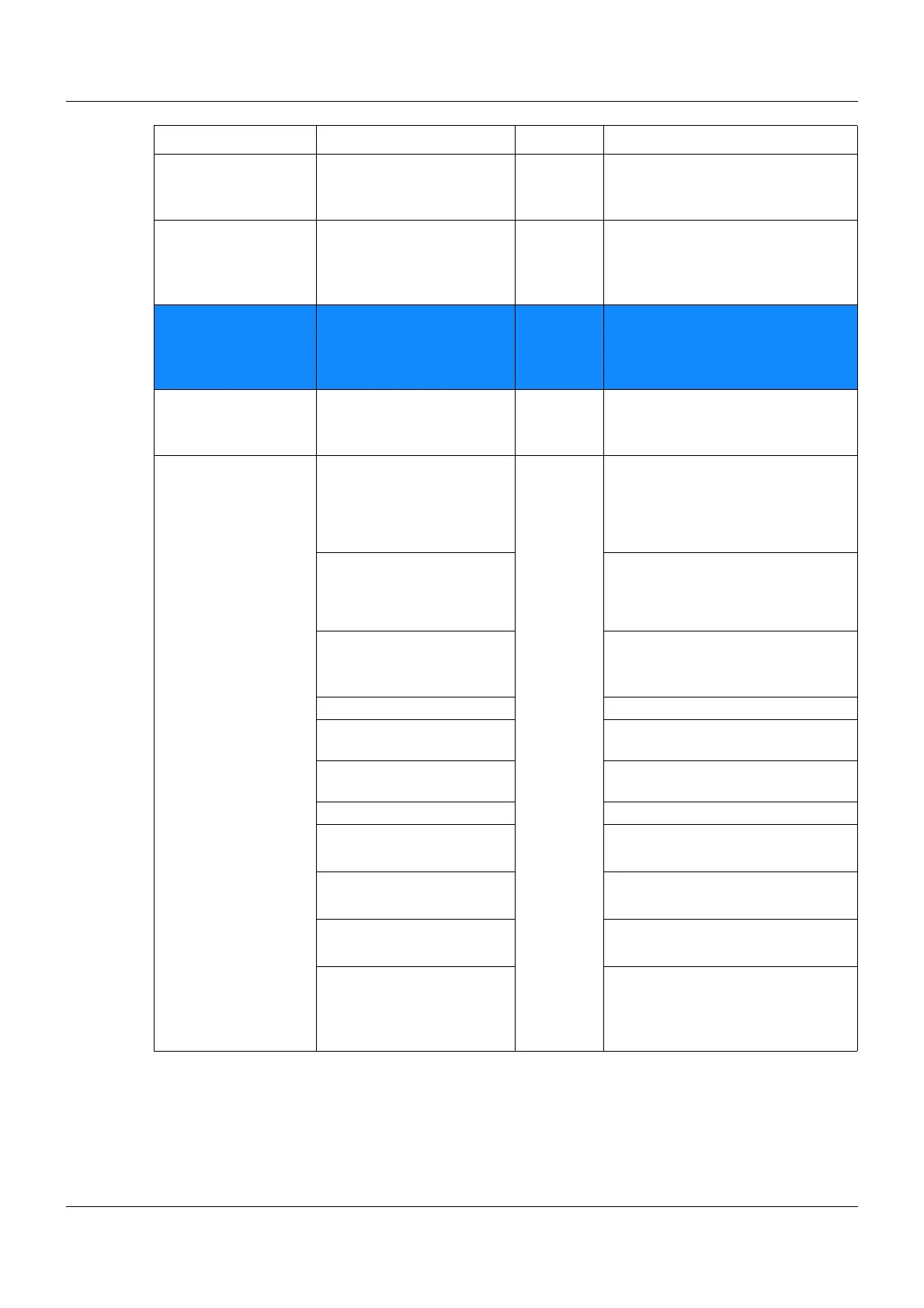
Ext. digital alarms Ext. digital alarm 1 to 8 External Alarms for ext. digital inputs
Ö Chapter 12.17 External digital
inputs Page 142
Digital control alarms Digital control alarm 1 to 8 Internal Alarms for the defined digital con-
trol signals 1 to 8
Ö Chapter 12.14 Digital controller
signals Page 135
Limit value alarms Limit value alarm 1 to 16 Internal Alarms for the limit value monitor-
ing function 1 to 16
Ö Chapter 12.9 Limit value moni-
toring function Page 106
Logic alarms Logic alarm 1 to 8 Internal Alarms for logic function 1 to 8
Ö Chapter 12.15 Math/logic Page
138
Alarm signals and
internal signals
Collective alarm Internal Collective alarm of the controller is
active, starting with the collective
alarm event to the end of the alarm
(as long as the red alarm line
flashes)
Collective alarm acknowl-
edged
Is active, starting with the collective
alarm event to the acknowledge-
ment of the alarm (as long as the
red bell is illuminated)
Memory alarm Memory alarm limit exceeded
Ö Chapter 12.3 Basic settings
Page 72
Malfunction
Fieldbus error Is active if PROFIBUS or PROFI-
NET report an error
Battery empty Buffer battery must be replaced by
JUMO Service
Battery pre-alarm Buffer battery voltage under 2.6 V
Login Logic level "0", user not logged in
Logic level "1", user logged in
USB inserted Logic level "0", USB not inserted
Logic level "1", USB inserted
Temp. in Fahrenheit Logic level "0", temp. not °F
Logic level "1", temp. in °F
Inside temperature too high Logic level "0", inside temperature
not too high
Logic level "1", inside temperature
too high
Category Signal Type Description