KRONE Operation Unit Alpha
97
Pos: 42.33 /Übersc hriften/Üb erschriften 4/A-E/ Einstellung d er Zuführpositio n @ 55\mod_12 94751304875_ 78.docx @ 5 33950 @ 4 @ 1
8.1.6.4 Adjusting the Feed Position
Pos: 42.34 /WHB/ Elektrik/Rundballe npresse/Alph a (Medium)/Ei nstellung der Z uführposition @ 8 3\mod_1 31710383388 0_78.docx @ 726 405 @ @ 1
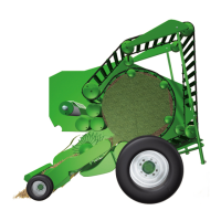
Fig.
1. The engine is extended up to the feed position with the key, i.e.:
• Move the motor out over the control unit just far enough so that there is still a small gap
between feeder plate (8) and conveyor roller (9). The dimension A between pivot point
of the ratchet (1) and operating lever (2) must be A = 285 mm.
In doing so, the right LED of the filling display (12) must light up. If the dimension A is
reached and the right LED of the filling indicator (12) lights up, save the feed position.
2. Use the key to save the value.
Read off the set value on the bar graph (11).
Pos: 42.35 /Übersc hriften/Überschrif ten 4/A-E/ Einstellung d er Abschneidep osition @ 55\ mod_1294751579 125_78.doc x @ 534002 @ 4 @ 1
8.1.6.5 Adjusting the Cut-off Position
Pos: 42.36 /WHB/ Elektrik/Rundballe npresse/Alph a (Medium) /Einstellung der Abschneidep osition @ 83\ mod_1317105156 120_78.doc x @ 726493 @ @ 1
The adjustment is made on the machine (refer to Chapter Default Settings and Operation
“Adjusting the Cut-off Position”).
RPN00044
A
1
2
AB CD EF GH
2
3
6
7
8
10
Fig.
1. The engine is retracted up to the cut-off position by using the key, i.e.:
• Move the engine in over the control unit just far enough so that dimension A between
the pivot point of the ratchet mechanism (1) and the adjusting lever (2) A = 410 mm and
the left pilot lamp of the filling indicator (12a) lights up.
2. Use the key to save the value.
Read off the set value on the bar graph (11).
Pos: 42.37 /La yout Module /---------------Seitenumbruch---------------- @ 0\mod_11961 75311226_0.doc x @ 4165 @ @ 1
 Loading...