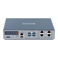
3: EMG 8500 Installation
EMG™ Edge Management Gateway User Guide 39
Hardware Specifications
Table 3-3 EMG 8500 Technical Specifications
Component Description
Serial Interface (Device)
Up to 8 RJ45-type 8-conductor connectors as up to two 4 port RJ45 I/O
modules can be installed. These connectors have individually configurable
standard and reversible pinouts, 4 ports per I/O module.
Speed software selectable (300 to 921600 baud)
Note: Serial RJ45 device ports for the EMG are reversed by default.
USB 2.0 Interface
(Device)
Up to 8 USB type A (Host) as up to two 4 port USB I/O modules can be
installed.
HS, FS, and LS
Capable of providing VBUS 5V up to 100 mA per port, but not to exceed 400
mA total per 4 port USB I/O module.
May be used with a USB-to-serial adapter to connect a serial device, if
needed. Please contact Lantronix for the list of tested adapters.
Caution: USB ports are designed for data traffic only. They are not
designed for charging or powering devices. Over-current conditions on
VBUS 5V may disrupt operations.
Serial Interface (Console)
(1) RJ45-type 8-pin connector (DTE)
Speed software selectable (300 to 921600 baud)
LEDs:
Green light ON indicates data transmission activity
Yellow light ON indicates data receiving activity
Network Interface
(2) 10/100/1000 Base-T RJ45 Ethernet with LED indicators:
Green light ON indicates a link at 1000 Base-T.
Green light OFF indicates a link at other speeds or no link.
Yellow light ON indicates a link is established.
Yellow light blinking indicates activity.
OR
(2) SFP ports to support standard fiber SFP transceiver modules (single or
multi-mode) at speed 1 Gigabit. with LED indicators:
Green light ON indicates a link is established.
Green light OFF indicates no link.
Yellow light steady ON indicates no activity.
Yellow light blinking indicates activity.
Note: Either Eth1 or SFP1 are active. Eth1 and SFP1 cannot both be active.
The same applies to Eth2 and SFP2.
Connectivity Modules
(2) connectivity slots to support 2 connectivity modules.
One LTE/4G cellular modem
One Wi-Fi module
One dialup modem
Power
Input: DC jack, 9-30 VDC (standard)
External AC (90W, 100-240V, 50/60 Hz) power supply shipped with unit
Dimensions
(L x W x H)
212.6mm [8.37”] x 167.68mm [6.60”] x 43.21mm [1.70”], 1U
Weight 1.406 kg (3.10 lbs)
Temperature
Operating: 0 to 50°C (32 to 122°F)
Storage: -20 to 80°C (-4 to 176°F)
Relative Humidity
Operating: 10% to 90% non-condensing
Storage: 10% to 90% non-condensing
 Loading...