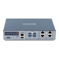
4: EMG 7500 Installation
EMG™ Edge Management Gateway User Guide 54
- For information about Lantronix adapters, see Appendix C: Adapters and Pinouts.
An available connection to your Ethernet network and an Ethernet cable CAT5E or better
cables are recommended for 1000 Base Ethernet.
An AC power outlet to power the unit using the included AC (90W, 100-240V, 50/60 Hz) power
supply.
If the LTE cellular modem is installed, a network SIM card (and data services) from a service
provider
Hardware Specifications
Table 4-2 EMG 7500 Technical Specifications
Component Description
Serial Interface (Device)
Up to 8 RJ45-type 8-conductor connectors
Two 4 port RJ45 I/O modules can be installed, one on the front and one
on the back of the unit.
These connectors have individually configurable standard and reversible
pinouts. 4 ports per I/O module.
Speed software selectable (300 to 921600 baud)
Note: Serial RJ45 device ports are reversed by default.
USB 2.0 Interface
(Device)
Up to 8 USB type A (Host) connectors
Two 4 port USB I/O modules can be installed, one on the front and one
on the back of the unit.
HS, FS, and LS
Capable of providing VBUS 5V up to 100 mA per port, but not to exceed 400
mA total per 4 port USB I/O module.
May be used with a USB-to-serial adapter to connect a serial device, if
needed. Please contact Lantronix for the list of tested adapters.
Caution: USB ports are designed for data traffic only. They are not
designed for charging or powering devices. Over-current conditions on
VBUS 5V may disrupt operations.
Serial Interface (Console)
(1) RJ45-type 8-pin connector (DTE)
Speed software selectable (300 to 921600 baud)
LEDs:
Green light ON indicates data transmission activity
Yellow light ON indicates data receiving activity
Network Interface
(2) 10/100/1000 Base-T RJ45 Ethernet with LED indicators:
Green light ON indicates a link at 1000 Base-T.
Green light OFF indicates a link at other speeds or no link.
Yellow light ON indicates a link is established.
Yellow light blinking indicates activity.
Connectivity Modules
One internal LTE/4G cellular modem
One Wi-Fi module or one dialup modem (optional configuration)
Power
Input: 9-30 VDC (standard)
External AC (90W, 100-240V, 50/60 Hz) 12VDC power supply shipped with
unit
Dimensions
(L x W x H)
163mm [6.4in] x 145mm [5.7in] x 43mm [1.7in], 1U
Weight 2.5 lbs
 Loading...