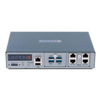
4: EMG 7500 Installation
EMG™ Edge Management Gateway User Guide 58
Walls Not Requiring Anchors
These instructions are for mounting the EMG to walls made of solid wood at least two (2) inches
thick.
(1) Wall mount:
1. Locate the place where you want to mount the unit and mark four holes using your EMG
mount as a guide for the screws. See for the location of the screw holes.
2. Drill four 3/16 inch (4.8 mm) diameter holes at a depth of 1.25 inches (32 mm).
3. Thread four pan head top mount screws through the unit mount hole and tighten them.
(2) Keyhole mount:
1. Locate the place where you want to mount the unit and mark two holes using your EMG mount
as a guide for the screws. See for the location of the screw holes.
2. Drill two 3/16 inch (4.8 mm) diameter holes at a depth of 1.25 inches (32 mm).
3. Thread two pan head top mount screws through the unit mount hole and reserve 0.08” to 0.12”
(2-3 mm) clearance to the wall surface.
4. Hang the EMG unit where both keyholes of wall mounts can go through the screw heads on
the wall.
Connecting to a Device Port
You can connect almost any device that has a serial console port to a device port on the EMG unit
for remote administration. The console port must support the RS-232C interface.
You may use a CAT5 cable, or a crossover cable if the reverse pinout function is not used.
Note: Many servers must either have the serial port enabled as a console or the
keyboard and mouse detached. Consult the server hardware and/or software
documentation for more information.
To connect to a serial RJ45 device port:
1. Connect one end of the cable to the device port.
2. Connect the other end of the cable to an RJ45 serial console port on the serial device or use a
Lantronix serial console adapter to connect it to other port types.
Notes:
See Device Port Commands on page 202 to enable or disable reverse pinouts
through the CLI.
Table 4-6 and Table 4-7 provide additional information on reverse pinouts.
See Appendix C: Adapters and Pinouts for information about Lantronix adapters.
Table 4-6 Console Port and Device Port - Reverse Pinout Disabled
Pin Number Description
1 RTS (output)
2 DTR (output)
3 TXD (output)
 Loading...