4: EMG 7500 Installation
EMG™ Edge Management Gateway User Guide 59
Table 4-7 Device Port - Reverse Pinout Enabled (Default)
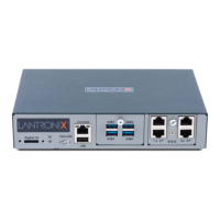
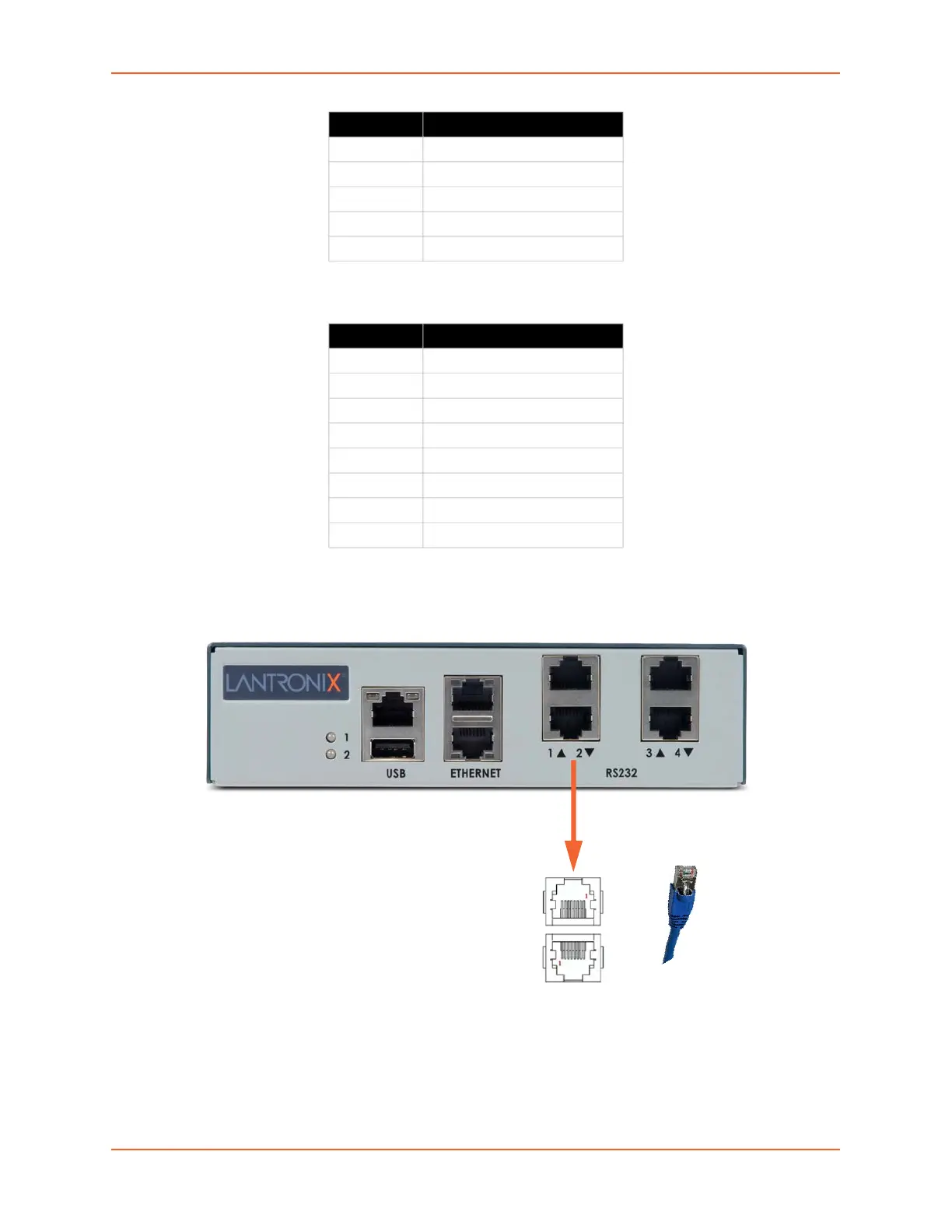
Figure 4-8 shows the front side of an EMG 7500 with a 4-port RJ45 device port module.
Figure 4-8 EMG 7500 (Front Side)
To connect to a USB device port:
1. Connect the USB type A connector of a USB cable to a device port.
2. Connect the other end of the USB cable to a USB console port.
4 Ground
5 Ground
6 RXD (input)
7 DSR (input)
8 CTS (input)
Pin Number Description
1 CTS (input)
2 DSR (input)
3 RXD (input)
4 Ground
5 Ground
6 TXD (output)
7 DTR (output)
8 RTS (output)
Pin Number Description
4-Port RJ45
I/O Module
 Loading...