3: EMG 8500 Installation
EMG™ Edge Management Gateway User Guide 40
Physical Installation
The EMG module uses convection cooling to dissipate excess heat.
To install the EMG unit:
1. If you have purchased additional I/O or Connectivity modules, install these modules.
For I/O modules, see I/O Module Installation (on page 49).
For Connectivity modules, see Connectivity Module Installation (on page 50).
Warning: The EMG must be powered off when installing or replacing the modules.
Not powering off the device before changing the module will void the
manufacturer warranty.
2. Mount the EMG unit.
If free-standing, attach the adhesive-backed rubber feet to the base of the EMG unit.
Place the unit securely on a desktop or other flat horizontal surface.
If rack-mounted, mount the unit securely in a 19-inch rack. See Rack Mount Installation
(on page 41).
If wall-mounted, mount the unit securely on a flat vertical surface. See Wall Mount
Installation (on page 42).
3. Connect the serial device(s) to the EMG unit’s device ports. See Connecting to a Device Port
(on page 44).
4. Choose one of the following options:
To configure the EMG using the network, or to monitor serial devices on the network,
connect at least one EMG network port to a network. See Connecting to Network Ports
(on page 46).
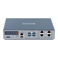
Front USB Port (1) port, type A, host USB 2.0 (HS, FS, LS) for use with flash drive
Front Memory Card (1) Secure Digital (micro SD) memory card slot supporting:
SD
SDHC
Internal Memory Optional: 128 GB Flash internal storage
Front DIO Port (1) Digital IO slot with two digital inputs and one relay output (terminal block)
LED Indicators
Ethernet port (upper LED on front panel)
Connectivity (lower LED on front panel)
RJ45 Ethernet (Activity/Link)
SFP (Activity/Link)
LTE Signal Strength
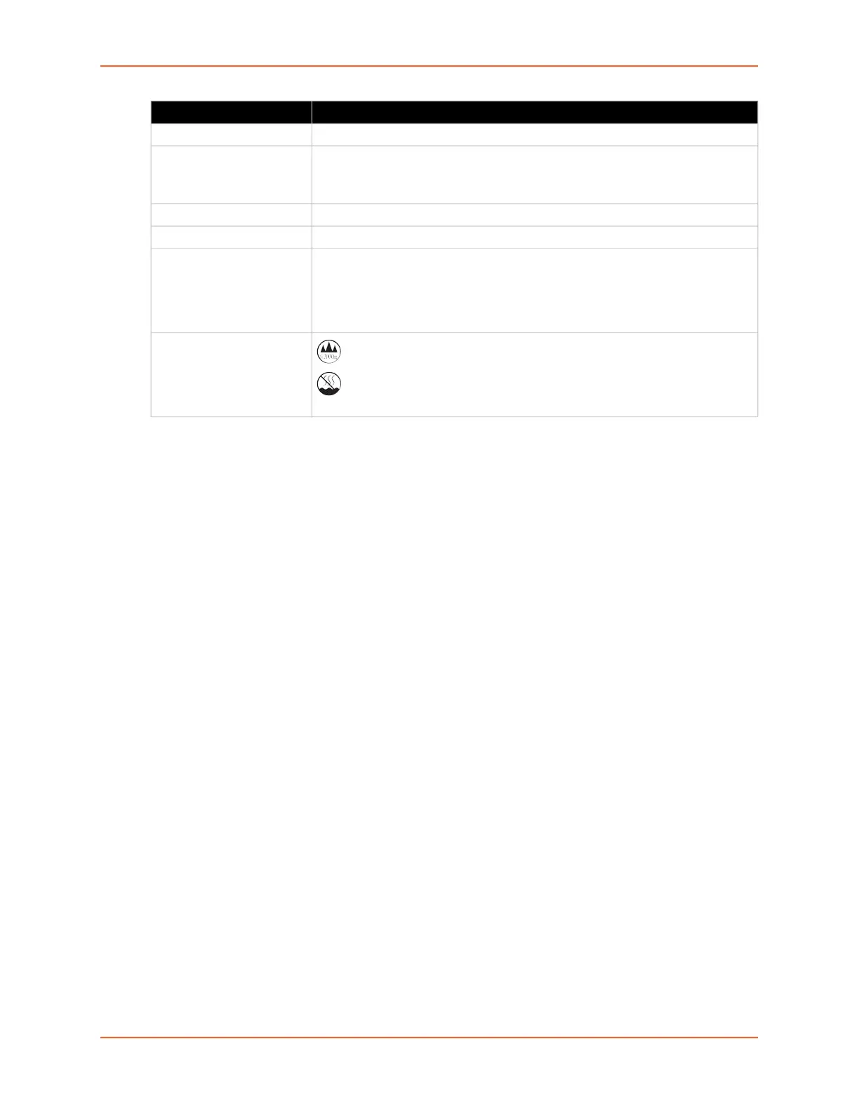
Operating Atmosphere
Caution: EQUIPMENT
IS FOR INDOOR USE
ONLY!
For use at altitudes no more than 2000 meters above sea level only.
For use in non-tropical conditions only.
Component (continued) Description
 Loading...