3: EMG 8500 Installation
EMG™ Edge Management Gateway User Guide 45
To connect to a USB device port:
1. Connect the USB type A connector of a USB cable to a device port.
2. Connect the other end of the USB cable to a USB console port.
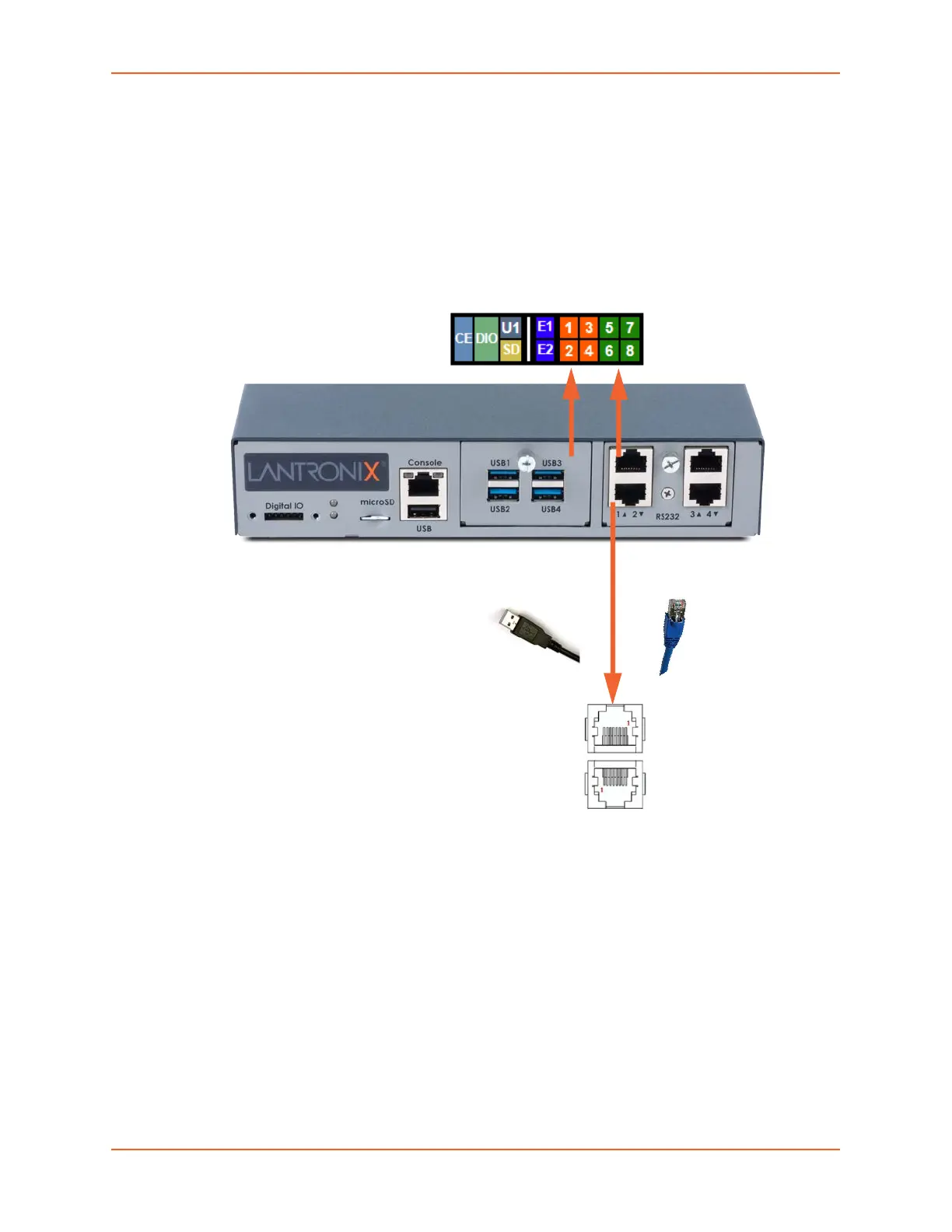
Figure 3-8 shows a sample I/O module installation with one 4-port USB I/O module in Bay 1 and
one 4-port RJ45 I/O module in Bay 2, and how the device ports correspond to the buttons on the
Web Manager Dashboard.
Figure 3-8 Sample Device Port Connections (Front Side)
Modular Expansion for I/O Module Bays
The EMG module configuration can be changed by adding or replacing I/O modules in the
I/O module bays. When populating the bays, Bay 1 and Bay 2 may be populated in any order and
one module may be left empty. The bays are ordered from left to right: Bay 1 is the slot next to the
console port and USB port and Bay 2 is the slot to the right of Bay 1. See Figure 3-8.
Any changes to the I/O modules must be done while the EMG unit is powered off. Table 3-9 shows
the available I/O module configurations. To install an I/O module, refer to I/O Module Installation
on page 49.
Warning: Install the I/O module on the front only of the EMG unit. Do not insert
any other module on the front of the EMG unit. Doing so may damage
the EMG unit and will void the manufacturer warranty.
4-Port USB
I/O Module
4-Port RJ45
I/O Module
Bay 1 Bay 2
Dashboard
 Loading...