262334 179 Revision A
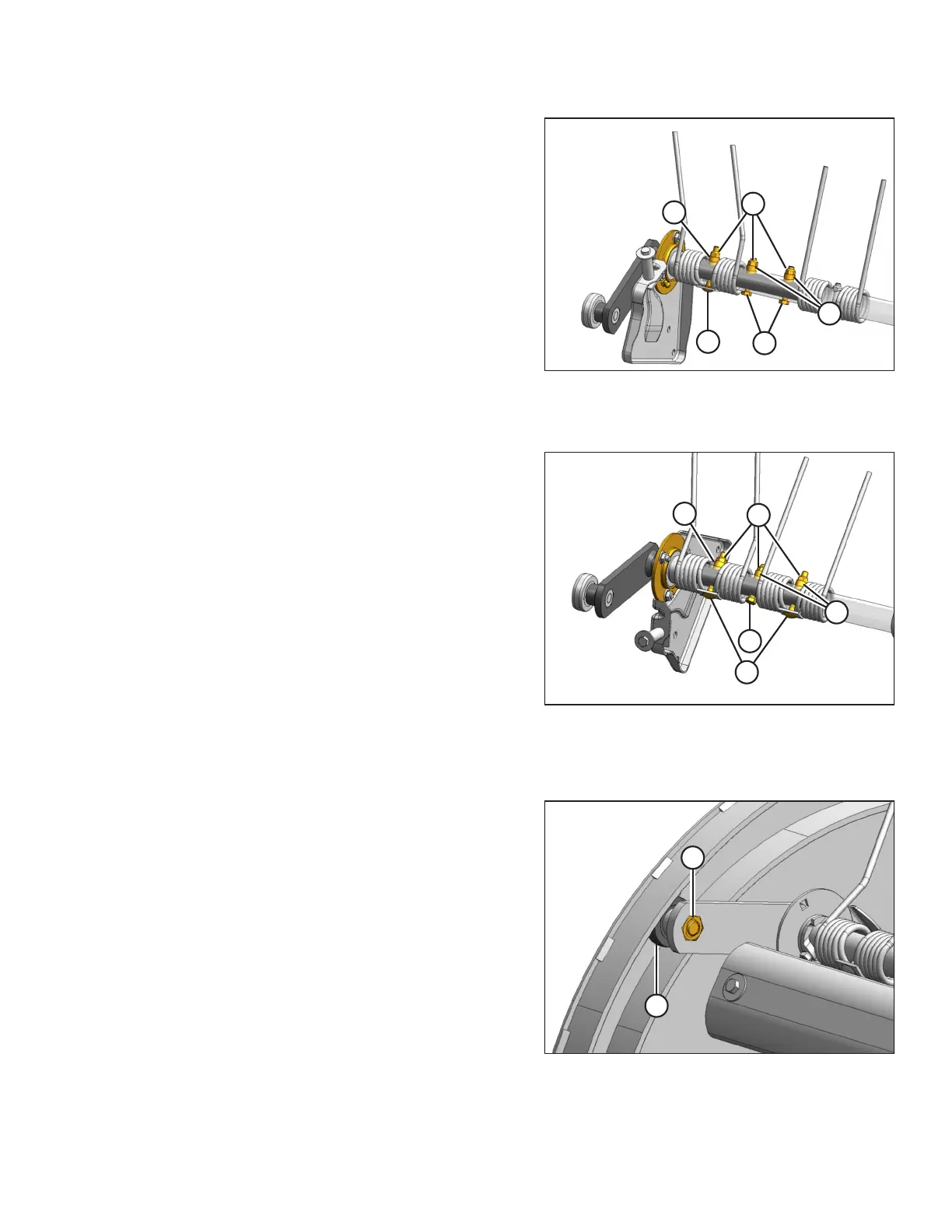
Figure 4.94: Type A Tine Bar
IMPORTANT:
Replace the hardware at the cam end of the tine bar with
the hardware as specified in the following steps.
13. Position the tines as shown and install bolts (A) with the
keepers, spacers (B), and nuts (C).
14. Install bolts (D), spacers (B), and nuts (C) between the tines
as shown.
15. Alternate the hardware configuration to include both Type
A Tine Bar and Type B Tine Bar configurations:
a. 5/16 x 2 1/2 in. carriage bolt (A)
b. Spacer (B)
c. Lock nut (C)
d. 5/16 x 2 in. hex head bolt (D)
Figure 4.95: Type B Tine Bar
A - Carriage Bolts B - Spacers
C - Lock Nuts D - Hex Head Bolt
Figure 4.96: Cam Arm Bearing
16. Install cam follower bearing (A) with bolt (B). Apply
medium-strength threadlocker (Loctite
®
262 or equivalent)
to the bolt threads, and torque the bolt to 122 Nm
(90 lbf·ft).
IMPORTANT:
Install the nut with the distorted thread TOWARDS the
bolt head.
MAINTENANCE AND SERVICING