INSTRUMENTATION/DRIVER INFO.
09–22–10
SPEEDOMETER CONTROL OUTLINE
CHU092255430S11
• The vehicle speed signal is output from the ABS HU/CM or DSC HU/CM to the microcomputer in the
instrument cluster.
End Of Sie
SPEEDOMETER CONTROL CONSTRUCTION/OPERATION
CHU092255430S12
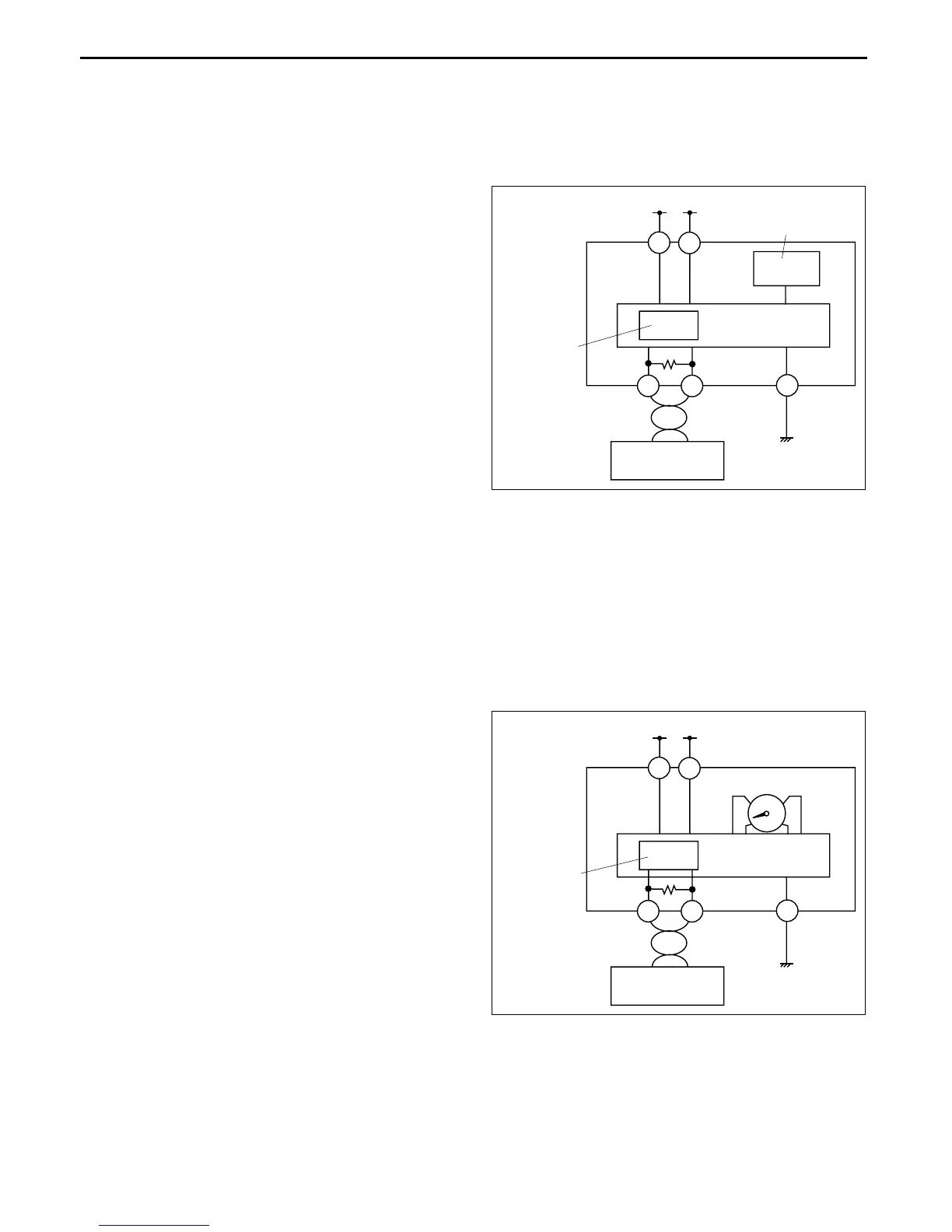
System Wiring Diagram
Operation
• The vehicle speed signal sent from the ABS HU/CM or DSC HU/CM via the CAN system is input to the
microcomputer in the instrument cluster. The microcomputer calculates the current vehicle speed based on the
vehicle speed signal, and sends an output signal to the speedometer.
End Of Sie
TACHOMETER CONTROL OUTLINE
CHU092255430S13
• The engine speed signal is output from the PCM to the microcomputer in the instrument cluster.
End Of Sie
TACHOMETER CONTROL CONSTRUCTION/OPERATION
CHU092255430S14
System Wiring Diagram
Operation
• The engine speed signal sent from the PCM via the CAN system is input to the microcomputer in the
instrument cluster. The microcomputer calculates the current engine speed based on the engine speed signal,
and sends an output signal to the tachometer.
End Of Sie
IG1
B+
1G
1E
1L1J
1C
CAN
CONTROL
CIRCUIT
ABS HU/CM or
DSC HU/CM
INSTRUMENT
CLUSTER
MICROCOMPUTER
SPEEDOMETER
CHU0922S104
IG1
B+
1G
1E
1L1J
1C
CAN
CONTROL
CIRCUIT
PCM
INSTRUMENT
CLUSTER
MICROCOMPUTER
TACHOMETER
CHU0922S105