INTAKE-AIR SYSTEM
01–13–15
01–13
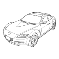
CHECK VALVE CONSTRUCTION/OPERATION
CHU011342910S02
• Composed of the main body and valve.
• Air can only flow from the vacuum chamber to the intake manifold.
End Of Sie
JET AIR FUEL MIXING SYSTEM OUTLINE
CHU011300113S08
• This system flows jet air (high-velocity air) into the primary port.
• Jet air is injected from the nozzle installed to the intake manifold, to blow off fuel adhering to the surface of the
intake port.
• A projection (anti-wet port) is provided on the bottom edge of the intake port. With this projection, air current is
formed so that the air-fuel mixture blown off by jet air flows to the intake port efficiently, and ideal air-fuel
mixture is obtained.
• The air/fuel ratio is lean due to the facilitation of a slow air intake velocity and low load fuel mixture. As a result,
fuel economy is improved.
End Of Sie
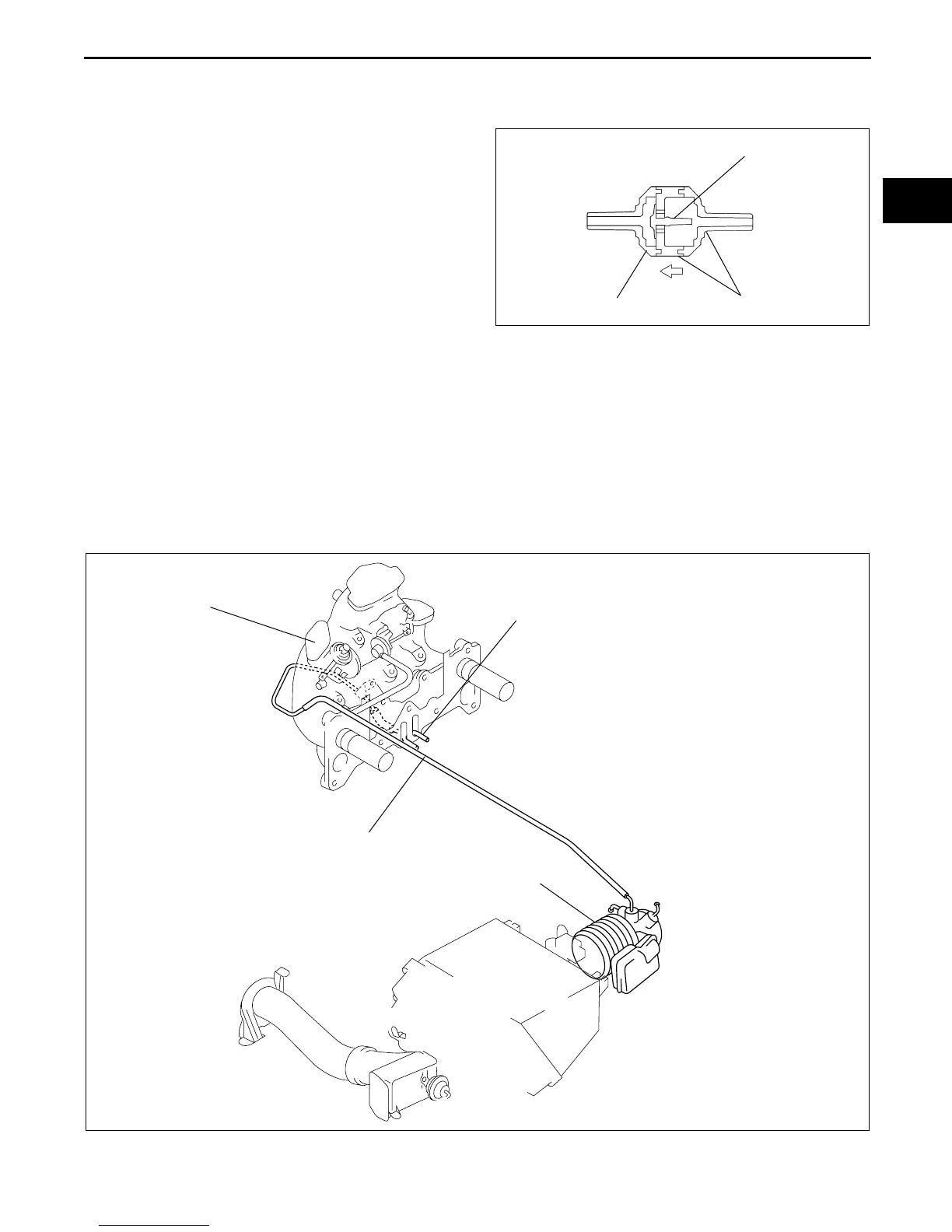
JET AIR FUEL MIXING SYSTEM CONSTRUCTION
CHU011300113S09
End Of Sie
VALVE
WHITE
GREEN
INTAKE
MANIFOLD
SIDE
VACUUM
CHAMBER SIDE
AIR FLOW
DIRECTION
CHU0113S023
NOZZLE
HOSE
AIR HOSE
INTAKE MANIFOLD
*: ILLUSTRATION SHOWS 13B-MSP (HIGH POWER)
CHU0113S024