CONTROL SYSTEM
09–40–6
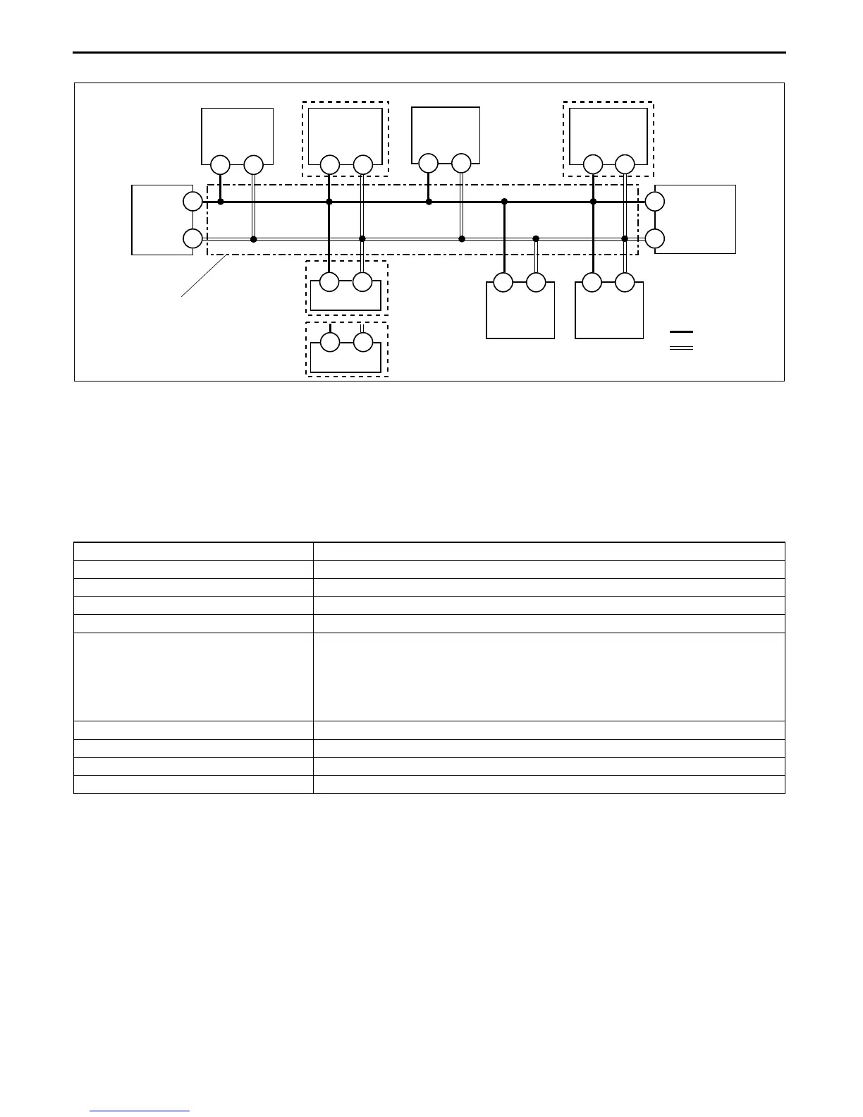
Block diagram
Failure detection function
• The failure detection function in each CAN system-related module detects malfunctions in input/output signals.
• This function outputs the DTC for the detected malfunction to the DLC-2, and also sends the detected result to
the memory function and fail-safe function.
Fail-safe function
• When the failure detection function determines that there is a malfunction, the fail-safe function illuminates a
warning light to inform the driver of the malfunction.
Memory function
• The memory function stores the DTC for the malfunction of input/output signals for related parts, as determined
by the failure detection function.
Self-malfunction diagnostic function
• The self-malfunction diagnostic function determines that there is a malfunction, and outputs a signal, as a DTC,
to the DLC-2. The DTC can be read out using an SST (WDS or equivalent).
PCM
INSTRUMENT
CLUSTER
ABS HU/CM
EPS
CONTROL
MODULE
TCM
AT
STEERING
ANGLE
SENSOR
WITH DSC
KEYLESS
CONTROL
MODULE
4S
4V
2M
2K
O
R
H
I
DSC HU/CM
WITH ABS
WITH DSC
3A
3B
1V
1Y
E
F
1J
1L
TWISTED PAIR
DLC-2
F
E
TPMS
CONTROL
MODULE
E
G
: CAN_H
: CAN_L
CHU0940S002
Module Fail-safe function
PCM • MIL illuminated
EPS control module • EPS warning light illuminated
TCM • AT warning light illuminated
ABS HU/CM (with ABS) –
DSC HU/CM (with DSC)
• ABS suspended
• TCS suspended
• DSC suspended
• ABS warning light illuminated
• DSC indicator light illuminated
• DSC OFF light illuminated
Keyless control module –
TPMS control module –
Steering angle sensor (with DSC) • Send malfunction data to DSC HU/CM
Instrument cluster • Speedometer, tachometer, water temperature gauge: 0 displayed
 Loading...